How to pick and integrate LRF modules
This practical guide helps B2B buyers, product managers, and integrators select and embed laser rangefinder (LRF) modules into UAVs (unmanned aerial vehicles), weapon scopes, and handhelds. We define key terms up front, compare 905 nm vs 1550 nm choices, outline electrical/firmware interfaces (e.g., MAVLink), and walk through compliance (IEC 60825-1 laser safety, CE/FCC, RoHS) and OEM/ODM delivery (MOQ, NRE, QA gates).
Table of Contents
ToggleDefinitions on first use:
-
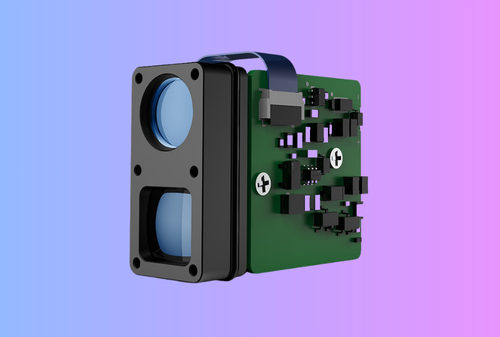
LRF (laser rangefinder): a time-of-flight (ToF) system that emits laser pulses and measures return time to compute distance.
-
OEM/ODM: Original Equipment Manufacturer / Original Design Manufacturer (build-to-spec or private-label).
-
UAV: Unmanned aerial vehicle (drone).
-
MPE: Maximum Permissible Exposure for laser safety per IEC 60825-1. MAVLink: an open messaging protocol widely used in drones; includes
DISTANCE_SENSORfor range data.
Executive Summary
-
Pick wavelength by mission, not hype. 1550 nm designs can operate at higher eye-safe power (higher ocular MPE) than 905 nm, enabling longer range at the same safety class; however, 905 nm can be less degraded in fog/rain and uses lower-cost Si detectors. Balance eye safety, weather, and BOM cost.
-
Design from the range equation outward. Start with target size/reflectivity and atmosphere, then choose pulse energy, aperture, receiver (APD/SPAD), and beam divergence. Use the LIDAR equation to stress-test range under attenuation and SNR thresholds. Interface early with your host system. For UAVs, publish ranges as MAVLink
DISTANCE_SENSOR; for scopes/handhelds, typical links are UART/CAN/I²C/USB plus GPIO for sync/laser interlock. Define message rates, units, timestamping, and fault codes up front. -
Engineer for shock, weather, and heat. Weapon recoil, gimbal vibration, and outdoor IP sealing drive lens mounts, PCB potting, and thermal paths. Select laser drivers and APDs with derating and ESD protections.
-
Compliance is non-negotiable. Classify the product to IEC 60825-1, label it, and keep the DoC/test reports for CE (EN 55032/55035) and FCC Part 15; confirm RoHS declarations for the optics/electronics. (This is not legal advice.)
Internal links for your team: explore our OEM/ODM Services, review Thermal Modules and Thermal Monoculars, or Contact Gemini Optics for integration kits.
1) Market & Buyer Needs: UAVs, Scopes, Handhelds
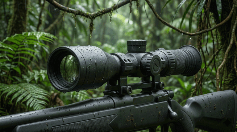
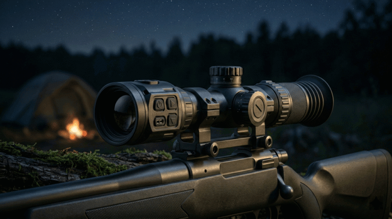
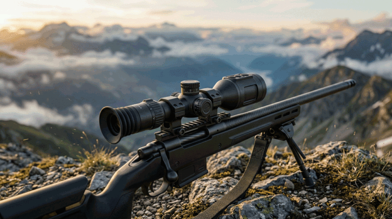
UAV payload integrators want light, low-power modules with deterministic latency, gimbal-friendly optics, and MAVLink output for mission computers. Scope builders (clip-on or embedded LRF scopes) prioritize recoil survivability, compact beam alignment to the sight axis, and ballistic app hooks. Handhelds need battery efficiency, ergonomic UX, and Bluetooth/Wi-Fi streaming.
Buyer personas:
-
Product Managers (PMs): balance spec vs. cost vs. lead time; push for eye-safe Class 1 at target ranges.
-
Hardware Leads: focus on thermal design, EMI/ESD, connectorization, and shock.
-
Firmware Leads: need simple APIs and deterministic timing for fusion (overlay, ballistics).
-
Sourcing: negotiates MOQs, NREs, license and compliance paperwork.
2) Key Technical Decisions
2.1 Wavelength: 905 nm vs 1550 nm (eye safety, detectors, weather)
-
Eye safety & power headroom. IEC 60825-1 allows substantially higher eye MPE at 1550 nm (SWIR) because ocular media absorb >1400 nm strongly—retinal exposure is minimized; this lets designers use higher pulse energy while staying Class 1, increasing range. Note: high-power 1550 nm can still damage cornea/lens—Class compliance and labeling are mandatory.
-
Detector ecosystem & BOM. 905 nm uses mature Si-APDs/Si-SPADs (lower cost); 1550 nm needs InGaAs receivers and different optics—raising price but enabling longer safe ranges at equal class.
-
Weather behavior. Studies and industry reviews indicate 905 nm can retain better performance in fog/rain vs 1550 nm (water absorption/scatter penalties are larger at 1550 nm), so adverse-weather priority may favor 905 nm.
Practical take: For civil UAVs needing eye-safe long-range mapping, 1550 nm often wins; for cost-sensitive scopes/handhelds with mixed weather, 905 nm remains attractive.
2.2 Range Budget: start with the laser radar equation
Use a first-order LIDAR equation to relate received power to pulse energy, target reflectivity, range, aperture, and atmospheric attenuation; then impose a detection SNR threshold to solve for Rmax. Sensitivity analysis (reflectivity 10–80%, visibility 1–20 km) quickly shows why 20% reflectivity and mist can cut range by >50% vs. a bright retroreflector.
Checklist for your range model: pulse energy & rep-rate; beam divergence; receiver aperture & responsivity; optical losses; electronics bandwidth; fog/rain extinction; background light; processing gain (averaging).
2.3 Optics & Beam Geometry
-
Beam divergence: Narrow beams concentrate irradiance for longer range but tighten alignment tolerances; wider beams ease aiming and reduce speckle, at the cost of peak irradiance.
-
Boresight & parallax: For scopes, keep the laser boresight within a few mrad of the sight axis and offer a simple digital zeroing routine. For gimbals, treat LRF as a co-boresighted sensor and calibrate to the EO/IR camera frame.
-
Apertures & windows: Use AR-coated windows matched to the wavelength band (e.g., fused silica for 905 nm; Infrasil/SWIR-optimized glass for 1550 nm). Maintain IP sealing with compliant gaskets.
2.4 Receiver & Signal Processing
-
APD vs. SPAD: Si-APDs/Si-SPADs are standard at 905 nm; InGaAs APDs at 1550 nm cost more but pair with higher transmit power. Use transimpedance amplifiers with carefully managed gain-bandwidth to minimize after-pulsing and ringing.
-
Discrimination: Use constant-fraction or CFD-like digital timing to reduce walk; median or matched-filter averaging for low SNR; multi-pulse voting to reject false returns (sun glints, aerosols).
-
Safety interlocks: Firmware must gate emission on laser-key, cover-closed, and class-limit checks; provide watchdogs and a hardwired interlock line per safety file. (Laser classes per IEC 60825-1.)
2.5 Interfaces & Protocols
-
UAVs: Publish ranges and status over MAVLink (
DISTANCE_SENSOR) with millisecond timestamps; include covariance or a quality metric so guidance can fuse it properly. Support heartbeat, health bits, and min/max range parameters. -
Scopes/handhelds: UART is simplest; CAN/CAN-FD for noise immunity and multi-node systems; USB for configuration/firmware; optional I²C for low-rate telemetry. Define SI units (m), packed endianness, and error codes early to avoid API drift.
Internal link: our integration reference kits and pin maps are available on the OEM/ODM Services page.
3) Reliability & Environmental Integration
-
Shock/recoil: For weapon-mounted systems, design lens barrels and PCBs to survive repeated recoil impulses; use steel thread inserts, elastomer cushions, and conformal coat sensitive components.
-
Vibration (UAV): Dampen high-Q modes on gimbals; add captive connectors; pot heavy inductors.
-
Thermal: Simulate laser-driver and APD heat; provide copper pours/heat spreaders; verify stability across -20 °C to +55 °C operation (or your target).
-
Ingress: Target IP66–IP67 class housings for rain/mud; separate pressure equalization from the optical path with hydrophobic vents.
-
EMI/ESD: Filter I/O lines, add TVS at the external connector, and maintain chassis-earth bonds across seams for CE/FCC margins.
4) Compliance & Documentation (summary only, not legal advice)
-
Laser Safety (IEC 60825-1). Classify (Class 1/1M/2/3R…) per emission, wavelength, exposure time, and optics; apply labels, user warnings, and include laser safety section in the manual. Keep a technical file with calculations and measurement reports.
-
CE EMC (EU). Demonstrate emissions to EN 55032 (CISPR 32) and immunity to EN 55035 (CISPR 35) as part of the EMC Directive; retain test reports in your Declaration of Conformity (DoC).
-
FCC Part 15 (US). Most LRF modules (with digital logic) are unintentional radiators under 47 CFR Part 15 Subpart B; authorize via SDoC/certification, label, and keep records. If you add radio (Wi-Fi/BLE), intentional radiator rules also apply.
-
RoHS. Ensure optics/electronics comply with Directive 2011/65/EU; collect supplier RoHS declarations of conformity for your tech file.
5) Procurement & Delivery
-
MOQ & price tiers: Expect evaluation units singly, then MOQs (often 50–100+) for custom optics/firmware.
-
Lead times: Optics coatings and APD/laser diodes can push 12–20 weeks in volume; buffer time for CE/FCC and laser safety testing (parallelize where possible).
-
NRE: Budget for custom lens/FOV, firmware features (e.g., ballistic API), and special housings.
-
QA milestones: EVT → DVT → PVT with incoming inspection (laser power, beam divergence), golden-sample images of spot profiles, and a burn-in/cycle test (emission duty plus temperature sweep). Keep traceability (serials, calibration data).
6) Application Playbooks
6.1 UAV Integration (gimbal/payload)
-
Mounting: Keep the transmit/receive path rigid; avoid window vignetting on gimbal extremes.
-
Timing: Publish 10–50 Hz ranges, include temperature/health; implement a fault bit when saturation, no-return, or interlock occurs.
-
MAVLink: Use
DISTANCE_SENSORfields for min/max, orientation, covariance; document frame IDs. -
Safety: Implement no-fire zones (e.g., when pointed at cockpit/crew during pre-flight), and a keyed laser enable.
6.2 Scopes (clip-on/embedded)
-
Recoil: Qualify on representative calibers (e.g., 7.62 NATO); pot lens groups; use thread-lockers.
-
User UX: One-hand ranging button, silent operation, and min/max hold readouts; optional API to ballistic solver.
-
Boresight: Provide a 2-point digital zero (near/far) and save profiles by optic.
6.3 Handhelds
-
Power: Prefer 18650/21700 packs; implement auto-sleep and display blanking to extend life.
-
Connectivity: USB-C for config/logs; optional Bluetooth LE for app readouts.
-
UX: Large font range readout, last-10 history, and quick unit toggle (m/yd).
7) Figure & Table
Figure 1 — Relative eye safety headroom (illustrative index)
Chart title: Relative Eye MPE at 905 nm vs 1550 nm (Illustrative Index)
Axes: x = Laser wavelength; y = Relative eye MPE (unitless index)
Note: Based on literature indicating 2–3 orders of magnitude higher eye-safe MPE at 1550 nm vs 905 nm; this figure is illustrative for design intuition, not a measurement.
Alt text: bar chart showing 905 nm = 1, 1550 nm ≈ 200 on a relative eye-MPE index.
-
Download chart image: mpe_relative.png
-
Re-plot from CSV: mpe_relative.csv
Table 1 — 905 nm vs 1550 nm LRF Modules (design trade-offs)
| Factor | 905 nm (NIR) | 1550 nm (SWIR) |
|---|---|---|
| Eye safety (MPE) | Lower ocular MPE → tighter power limits at Class 1. | Much higher ocular MPE allows higher eye-safe power, aiding range (still requires proper classing/labels). |
| Detectors | Si-APD/Si-SPAD (mature, lower cost). | InGaAs APD/SPAD (higher cost, better paired with higher TX power). |
| Weather (fog/rain) | Often less degraded in fog due to lower water absorption/scatter. | Can be more degraded in fog/rain; needs more TX power for same range. |
| Compliance | Same IEC 60825-1 framework; common to achieve Class 1 at moderate ranges. | Same framework; typically easier to hit Class 1 at longer ranges (thanks to higher MPE). |
| BOM & supply | Broad, cost-efficient ecosystem. | Higher component cost (InGaAs optics/receivers). EE Times |
| Use cases | Cost-sensitive scopes/handhelds, mixed weather. | Eye-safe long-range UAV mapping; premium handhelds/scopes. |
8) FAQ
Q1. Is 1550 nm “automatically eye-safe”?
A. No. 1550 nm can support much higher eye-safe power than 905 nm because retinal exposure limits are higher, but Class 1 still requires meeting IEC 60825-1 limits; cornea/lens damage is possible at excessive power. Always classify, label, and interlock. laserfocusworld.com
Q2. Does 905 nm always outperform 1550 nm in bad weather?
A. Not “always,” but multiple analyses show 905 nm can have less fog attenuation, while 1550 nm benefits from higher allowed power in clear air. Model both conditions for your mission, not just clear-day range.
Q3. How should we publish UAV ranges?
A. Use MAVLink DISTANCE_SENSOR with timestamps, orientation, min/max, and a quality/covariance field; include a status bit for saturation/no-return.
Q4. What minimum documents do we need for CE/FCC?
A. EMC test reports (EN 55032 emissions + EN 55035 immunity) for CE, an EU DoC, and Part 15 Subpart B authorization for FCC, plus laser safety classification per IEC 60825-1 and RoHS declarations in your technical file.
Q5. How do we align an LRF to a scope’s optical axis?
A. Provide mechanical boresight within a few mrad, then a digital two-point zero (near/far) routine storing offsets in NVM. Lock the mount with inserts and thread-locker to preserve alignment under recoil.
Q6. What interlocks are typical?
A. Hardware: laser-enable key, cover-closed, over-temp, and watchdog to cut emission. Firmware: emission only when class-limit calculations pass, with fault codes on any safety trip (documented in the API).
Q7. Can we share the same module across UAV/handheld/scope?
A. Yes—use a common core (laser/receiver/MCU) with variant I/O harnesses, different lens barrels, and firmware features toggled per SKU. Qualify recoil on scope SKUs and EMI/ESD on handheld/UAV SKUs.
Q8. What’s the best quick test for a module sample?
A. Verify range vs. reflectivity on three targets (high-reflectance board, matte cloth, foliage) at fixed distances; measure stability over temperature; and log no-return handling (timeouts, status bits). Use the same targets later for production QA comparability.
9) Conclusion & CTA
Choosing and integrating a laser rangefinder module is about mission-fit: wavelength trade-offs (905 nm vs 1550 nm), range budget under real atmospherics, robust interfaces (MAVLink/UART/CAN), and non-negotiable compliance. With a disciplined OEM/ODM plan—clear requirements, milestone QA, and a tidy tech file—you’ll ship on time and scale confidently.
Ready to accelerate your build with a partner who ships LRFs alongside thermal modules and optics?
CTA (pick one):
-
Book a technical design review — share your FOV, range, and host interface; we’ll map a module spec and test plan.
-
Request an evaluation kit/sample — bench-test a 905 nm or 1550 nm module with our harness and demo app.
-
Get the integration bundle — CADs, pin maps, MAVLink examples, and safety file templates.
Start here: OEM/ODM Services · Thermal Modules · Contact Gemini Optics