FPV payloads don’t live on islands—they must plug into flight controllers, companion computers, and industrial systems. This practical guide shows OEM/ODM teams how to connect an FPV Thermal Imaging Module to PLC/CAN/Ethernet networks with clean power, stable timestamps, and channel-ready documentation.
Table of Contents
ToggleExecutive Summary
- Pick protocols by job, not habit. Use UART/CAN for low-latency control and telemetry on-airframe; use Ethernet for high-throughput video/analytics and plant/SCADA integration.
- Speak the plant’s language. For factory and utility buyers, OPC UA (IEC 62541) and Modbus TCP/RTU remain the safest bets for SCADA/PLC connectivity and long-term interoperability.
- Align clocks before data fusion. ROS 2 nodes use a middleware layer (DDS) and a unified time model; keep thermal frames stamped with event time and bridge that clock into your PLC/CAN/Ethernet gateways to avoid “swim” in overlays and logs.
- Respect fieldbus physics. CAN (ISO 11898) requires correct termination and cabling discipline; Ethernet-based industrial networks (e.g., EtherNet/IP) build on IEEE 802.3 and the TCP/IP suite—use switches and grounding that match industrial EMI.
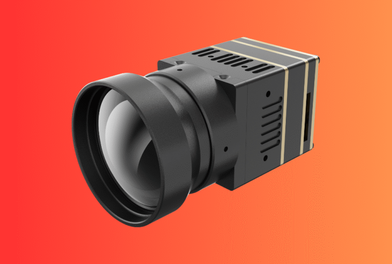
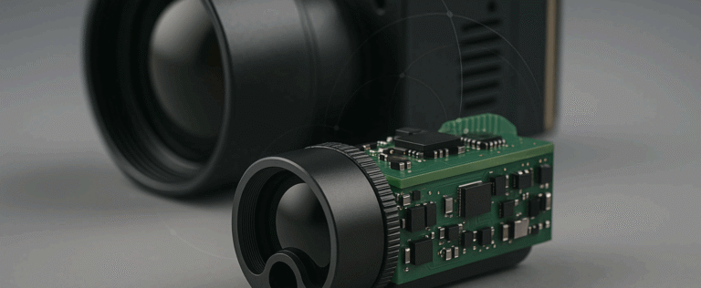
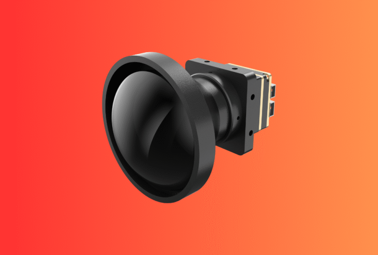
Start with our Thermal camera module. If you plan to add distance and confidence overlays later, our Laser Rangefinder Module drops into the same interface stack.
Use Cases & Buyer Scenarios
Utility and industrial inspection (plant or substation)
Thermal frames and alarms flow to a PLC/SCADA room via Ethernet (Modbus TCP or OPC UA). On-airframe control stays on UART/CAN; a companion computer aggregates and forwards logs for maintenance audits.
Public-safety fleets and training centers
Fleet managers want per-serial CSV/JSON logs and live HUD video on a wall display. Use Ethernet multicast to a monitor node; archive OPC UA variables for after-action reviews. Handheld confirmation with Thermal Monoculars or Thermal Binoculars keeps operations tight.
System integrators building fixed FPV nests
Fixed FPV perches on plant roofs stream thermal ROI alarms to PLCs for automated sirens/lighting. A CAN-to-PLC bridge handles arm/disarm, while Ethernet carries video snapshots and long-form logs to historians.
Spec & Selection Guide (the heart)
What to standardize in your SOW/RFQ
-
Interfaces on-airframe: UART for control; CAN 2.0/FD when you need robust, multi-node telemetry.
-
Industrial interfaces: RS-485 Modbus RTU for legacy PLCs; Ethernet (Modbus TCP / OPC UA / plain TCP-JSON) for modern plants.
-
Data model: topic/variables for
t_event_ns, fps, palette_id, temperature_px (optional ROI), supply_mv, status. -
Throughput & latency: required fps, max latency (HUD), log batching interval.
-
Time base: single clock domain; mapping of event time → PLC timestamp.
-
Cabling & EMC: CAN length/termination, Ethernet shielding/PoE plan, ground strategy.
Quick comparison—interface options for FPV thermal payloads
| Link | Best use | Typical payload | Latency feel | Cable length | Stack complexity | Notes |
|---|---|---|---|---|---|---|
| UART | Module control, simple telemetry | kB/s | Very low | <1–2 m | Low | Easiest on airframe; bridge to higher layers later. |
| CAN 2.0/FD | Robust multi-node bus on airframe | tens–hundreds kB/s | Low | 5–40 m | Medium | Terminate 120 Ω each end; twisted pair; ISO 11898. |
| RS-485 Modbus RTU | Legacy PLCs | kB/s | Medium | 100–1000 m | Medium | Simple registers/coils; master-slave. |
| Ethernet TCP/UDP | Video, bulk logs, gateways | MB/s | Medium | 100 m per hop | Medium | General-purpose; align 802.3/PoE/EMI. |
| Modbus TCP | Fast PLC/SCADA polling | kB/s | Medium | 100 m per hop | Medium | Easy migration path from RTU. |
| OPC UA | Semantic plant integration | kB/s–MB/s | Medium | 100 m per hop | Higher | Standardized info models; security built-in; IEC 62541. |
If/Then decision
If plant = legacy PLC only → export Modbus RTU (RS-485) + gateway to Ethernet later.
If plant = modern SCADA/IT → expose OPC UA variables for alarms/temperatures + JPEG snapshots via HTTP/MQTT.
If link must survive noise/length on-airframe → use CAN 2.0/FD; bridge to Ethernet at the companion.
If video/HUD needs lab viewing → add Ethernet multicast; keep UART/CAN for control paths.
Always stamp frames with event time → map to PLC/SCADA timestamps at the gateway.
Integration & Engineering Notes
Electrical & Interfaces
-
Segregate rails and grounds. Put the VTX and compute on low-noise rails with LC filters; star ground to avoid banding.
-
CAN discipline. Twisted pair, 120 Ω termination at both ends, and common-mode chokes near connectors; avoid long stubs.
-
Ethernet choices. For fixed nests, consider PoE to simplify cabling; for mobile rigs, short patch leads to a companion SBC reduce strain.
-
Gateway patterns.
-
UART/CAN → SBC → Modbus TCP server or OPC UA server.
-
Ethernet camera stream + JSON telemetry → MQTT broker → plant IT.
-
Planning range overlays? The same UART/CAN channel can carry our Laser Rangefinder Module data; expose
range_mandconfidenceas Modbus/OPC UA nodes.
Optics & Mechanics (mounting, alignment, sealing)
-
Connector access. Place service loops and strain relief near the companion gateway; add locking connectors for CAN/Ethernet.
-
Isolation. Tune elastomer standoffs to the frame’s vibration spectrum; avoid over-soft mounts that drift boresight.
-
Enclosures. AR/anti-fog windows, gasket torque spec, and IP-level appropriate to outdoor nests.
Firmware/ISP/Tuning (AGC, palettes, data model)
-
Stable semantics. Document the variable list (names, units, min/max) once—Modbus map and OPC UA nodes mirror the same model.
-
Event time first. Publish
t_event_nswith each frame and ROI reading; never infer from publish time. -
Alarms. Gate high-temperature alerts with persistence (e.g., 0.5 s) to avoid yaw-flicker false positives.
H3: Testing & Validation (bench → field)
-
Throughput & jitter. On bench, stream thermal frames while polling Modbus/OPC UA; record latency and jitter histograms.
-
CAN robustness. Introduce motor noise and check error counters/bus-off behavior; verify that the node recovers gracefully.
-
End-to-end SAT. Save a 10–20 s dusk pan video plus CSV/JSON logs; confirm PLC/SCADA shows the same
t_eventtimeline.
Compliance, Export & Certifications
-
Dual-use/export controls. Thermal cameras with higher frame rates can be controlled (e.g., US ECCN 6A003); the EU’s Regulation (EU) 2021/821 is the dual-use legal basis—classify before quoting and shipping.
-
Industrial Ethernet conformance. Protocols like EtherNet/IP ride on IEEE 802.3—use certified switches/cabling and respect grounding to pass EMC and keep links stable.
-
Materials & EMC pack. Prepare CE/FCC/UKCA reports plus RoHS/REACH declarations in the same binder as your Modbus/OPC UA maps.
Building handheld validation kits for crews? Cross-sell Thermal Clip-On Sight and Thermal Rifle Scopes to field teams who want familiar thermal UX.
Business Model, MOQ & Lead Time
-
Samples & gateways. 2–4 weeks for standard modules and a Linux gateway image (Modbus TCP / OPC UA); 4–6 weeks for custom nodes and dashboards.
-
MOQ. 50–200 pcs baseline; ≥300 pcs for custom housings/windows or PoE nests.
-
Deliverables. Module + harness + mounts, SDK + data model, gateway image (Modbus/OPC UA), acceptance scripts, and a per-serial video/CSV clip.
Mini ROI model—why PLC/CAN/Ethernet readiness pays
| Driver | Before integration | After integration | Units/yr | Annual impact |
|---|---|---|---|---|
| Plant hookup time | 2–3 days | <1 day | 50 sites | ↓ truck rolls |
| NFF returns | 1.0% | 0.5% | 2,000 | −10 RMAs |
| Bid win rate on industrial RFPs | Baseline | +10–15% | — | OPC UA/Modbus maps in RFP |
| Support cases per 100 units | 6 | 3 | — | −50% load |
Pitfalls, Benchmarks & QA
Seven mistakes to avoid
-
No unified data model. Modbus map ≠ OPC UA nodes → integrators rewrite code; define once, generate both.
-
Ignoring event time. Logs drift across PLC/flight recorder; always map sensor capture time into PLC/SCADA.
-
CAN stubs and bad terminations. Bus errors and “ghost” faults; follow ISO 11898 rules and terminate correctly.
-
Dirty grounds. Video banding and packet loss when VTX shares a noisy rail; isolate and filter.
-
Ethernet like office IT. Industrial EMI and long runs need shield, bonding, and certified switches (e.g., for EtherNet/IP).
-
Security is an afterthought. OPC UA offers built-in security—enable certificates and user auth from day one.
-
Undefined acceptance. No SAT means subjective debates; ship a three-scene test and variable-log template.
Benchmarks to record
-
Throughput & jitter on serial and Ethernet paths.
-
Bus health on CAN (error counters, bus-off frequency).
-
Latency to PLC/SCADA: time from
t_eventto updated coil/node. -
Packet loss under motor noise and Wi-Fi saturation.
FAQs
1) Which protocol should I expose first for industrial buyers—Modbus or OPC UA?
If the plant is legacy-heavy, Modbus RTU/TCP wins speed to value. For greenfield or multi-vendor analytics, OPC UA (IEC 62541) provides semantic interoperability and built-in security.
2) Can I run both Modbus TCP and OPC UA from one gateway?
Yes. Mirror the same variables into both servers; keep t_event_ns as the authoritative time.
3) How do I keep overlays from “swimming” when I bridge to PLCs?
Stamp frames with event time at capture and propagate unchanged to the gateway; ROS 2’s time model makes this straightforward.
4) Do I need CAN FD or is CAN 2.0 enough?
For terse telemetry and commands, CAN 2.0 is fine; choose CAN FD if you push larger payloads or want future headroom.
5) What about Industrial Ethernet variants like EtherNet/IP?
They build on IEEE 802.3 and TCP/IP; use industrial-grade switches/cables and follow vendor conformance guidance to pass EMC and keep links reliable.
6) Can we power a fixed nest over one cable?
Yes—PoE simplifies installation; ensure thermal and surge protection are designed for your roof or mast environment.
7) How do we hand logs to compliance teams?
Export CSV/JSON with t_event_ns and ROIs; many teams ingest these into historians or SIEMs with minimal work.
Share your airframe, PLC/SCADA environment, and target variables. We’ll deliver a turn-key FPV thermal interface pack—module, low-noise power, CAN/UART harness, and a Linux gateway image exposing Modbus TCP and OPC UA—plus an upgrade path to add range via our Laser Rangefinder Module.