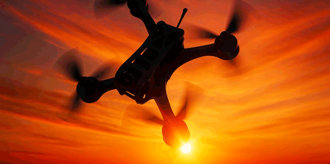
Build an FPV payload that pilots actually trust. This guide shows OEM/ODM teams how to pair an FPV Thermal Imaging Module with a low-latency HUD and a clean SDK/OSD bridge—so overlays stay readable, time-aligned, and ready for scale across fleets.
Table of Contents
ToggleExecutive Summary
- Design for end-to-end latency. Budget the digital FPV link and your overlay pipeline; align everything to a single clock (ROS 2
/clockor autopilot time via MAVLinkTIMESYNC). - Use event time, not publish time. Stamp frames when the sensor captures them and pass timestamps through your SDK → HUD → goggles chain.
- Choose an OSD path you control. Betaflight/INAV MSP DisplayPort “canvas” lets you draw text/graphics at exact coordinates—ideal for thermal cursors, hotspots, and alerts.
- Keep the UI simple. A minimal HUD (temperature cursor, palette tag, confidence bar) beats busy overlays that add lag and obscure the scene.
- Package for channels. Document APIs, acceptance tests, and export notes for thermal modules; this accelerates onboarding in US/EU markets.
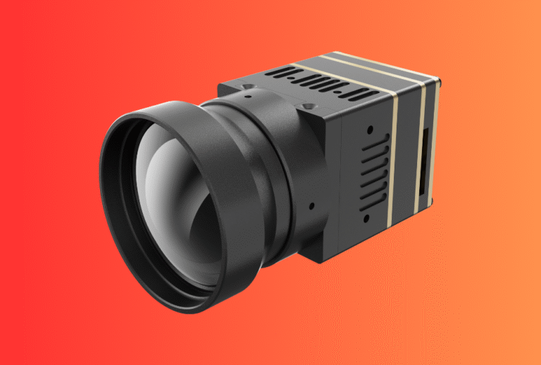
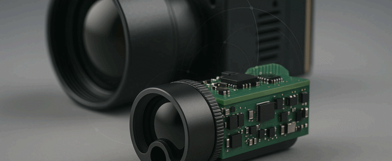
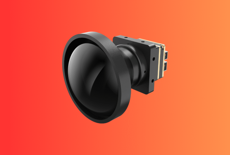
Explore our Thermal camera module lineup. If you plan to add absolute distance later, pair with our Laser Rangefinder Module for fused thermal + range HUD.
Use Cases & Buyer Scenarios
Public safety and SAR teams (night FPV)
Need fast detection of warm targets around rooftops and tree lines. A simple HUD with temperature cursor and confidence bar reduces cognitive load during search patterns. Pair with handhelds like Thermal Monoculars for ground confirmation.
Infrastructure inspection (utilities, rooftops, solar)
Pilots want stable overlays during slow orbits and close approaches. Time-aligned thermal frames + clear alarms (e.g., “>80 °C hotspot”) help decide whether to land and inspect. For two-person crews, Thermal Binoculars support ground verification.
Product demo and training fleets
OEM/ODM teams need repeatable HUD behaviour across many rigs. MSP canvas + consistent palettes enable the same look-and-feel on different airframes and VTX systems.
Spec & Selection Guide
Key parameters that decide if your FPV thermal HUD will work in the field
-
Sensor & optics: 256×192 or 384×288 is common for FPV overlays; pair focal length to typical standoff (FOV vs target size).
-
NETD: Lower mK = better sensitivity; choose ≤50 mK for clean overlays at dusk.
-
Frame rate: 25–50 fps feels smooth; remember some jurisdictions treat >9 Hz thermal modules as controlled dual-use.
-
Timestamping: Your SDK should expose
t_event(capture time). ROS 2 uses/clockandHeader.stamp; autopilots can sync via MAVLinkTIMESYNC. -
OSD method: MSP DisplayPort “canvas” or telemetry-driven OSD; the former gives precise placement and richer graphics.
-
Power/EMI: Keep the HUD processor and digital VTX clean—use low-noise rails and LC filters to avoid banding and dropped frames.
Comparison—three overlay approaches (pick one)
| Overlay path | Latency control | Graphics flexibility | Dependency | Notes |
|---|---|---|---|---|
| MSP DisplayPort canvas | High (you draw per frame) | High (text, icons, bars at XY) | FC firmware & VTX MSP support | Best balance for FPV HUDs. |
| Telemetry-driven OSD | Medium | Medium (vendor panels) | Vendor firmware updates | Faster to start, less control. |
| Goggle-side app overlay | Variable | High | Vendor SDK or reverse-bridge | Useful for demos; QA harder across goggles. |
Decision rules
If you control FC firmware/VTX → use MSP DisplayPort canvas for precise HUD.
Else if you need fast POC → use telemetry OSD, accept limited widgets.
Always align time first:
– ROS 2 nodes follow /clock (set use_sim_time consistently), and
– Companion ↔ autopilot run MAVLink TIMESYNC.
Then keep HUD minimal (cursor, palette tag, confidence bar) to protect latency.
Integration & Engineering Notes
Electrical & Interfaces (UART/USB/CAN/SDK)
-
Clean power for video & compute. Use low-noise buck with LC filtering; isolate VTX and compute rails where possible.
-
Throughput vs jitter. If grabbing frames over USB/MIPI, measure delivery jitter—HUD “swim” often tracks host jitter, not sensor FPS.
-
SDK fields: expose
t_event_ns,temperature_px,palette_id, optional hotspot candidates (x, y, T, conf).
Optics & Mechanics (mounting, alignment, sealing)
-
Datum first. V-groove/dowel pins help boresight repeatability after service.
-
Vibration isolation. Elastomer standoffs reduce micro-blur; over-soft mounting can drift alignment.
-
Window & coatings. For enclosed payloads, specify AR/anti-fog; torque consistency avoids image tilt.
Firmware/ISP/Tuning (AGC, palettes, HUD)
-
AGC presets. Offer “linear”, “histogram”, and “target-lock” modes; document default LUT to standardize colour language across fleets.
-
HUD widgets. Keep to 3 primitives: temperature cursor, palette tag, confidence bar. Add alarms only when thresholds persist >N frames.
-
Frame timing. Publish both frame index and
t_event; if your FC runs an autopilot, bridgeTIMESYNCoffset into your renderer.
Testing & Validation (bench → field)
-
Latency budget: Measure sensor→HUD→goggle using a blinking heat source and a photodiode on the display; aim for consistent delta across rigs.
-
Acceptance clip: Save 10–20 s video per serial (indoor hot/cold plates + outdoor dusk pan) with power draw and FPS.
-
In-flight QA: A short hover-pan test verifies overlay stability before missions.
Compliance, Export & Certifications
-
Dual-use/export: Thermal imaging modules can be controlled items. The EU’s Regulation (EU) 2021/821 governs dual-use exports and is updated annually via delegated regulations; check the current list before shipping.
-
System documentation: Even when the thermal module is ≤9 Hz (less controlled in some jurisdictions), keep CE/FCC/UKCA and RoHS/REACH documents together in a compliance pack for channel onboarding.
-
If adding a laser later: plan for IEC 60825-1 classification and label proofs under the same program you use for EMC/materials.
Business Model, MOQ & Lead Time (OEM/ODM)
-
Sampling: 2–4 weeks (standard lenses, stock SDK); 4–6 weeks if you need custom palettes/HUD graphics.
-
MOQ: 50–200 pcs for baseline; 300+ for custom housings/windows.
-
Deliverables: module + harness, SDK docs, MSP scripts, acceptance checklist, and a short “how-to overlay” video.
-
Mini ROI model for agencies/distributors
| Driver | Before HUD | After HUD | Units/yr | Impact |
|---|---|---|---|---|
| Operator dwell per hotspot | 14 s | 8 s | 1,000 sorties | ↑ mission throughput |
| Training time to competency | 6 h | 3.5 h | — | ↓ onboarding cost |
| NFF returns (no-fault-found) | 1.0% | 0.5% | 2,000 units | −10 RMAs |
Pitfalls, Benchmarks & QA
Common mistakes (and fixes)
-
Mixing time domains (system vs ROS time): set
/clock&use_sim_timeconsistently; bridgeTIMESYNCoffset to your renderer. -
Busy overlays that add lag: cut to three widgets; defer analytics to ground.
-
Noisy power rails causing banding/drops: add LC filters; separate VTX and compute rails.
-
Unstable boresight after service: use datums and a two-point re-zero.
-
Undefined acceptance: require a 3-scene video clip + power/FPS log per serial.
Benchmark methodology—detection vs recognition vs identification
-
Detection: hotspot appears and persists ≥N frames at confidence ≥C.
-
Recognition: operator can distinguish a class (e.g., human vs vehicle) at defined distance/FOV.
-
Identification: specific object features (e.g., person with backpack) under stable exposure.
Use the same scenes across lots; archive clip + metadata with serial for traceability.
FAQs
1) What’s the practical latency target for FPV thermal HUDs?
Keep the sensor→HUD→goggle path consistent and time-aligned; digital FPV adds its own delay, so align to a shared clock and keep HUD work minimal. ROS 2 /clock and MAVLink TIMESYNC help here.
2) Which OSD method is best to start with?
If you control the FC and VTX, MSP DisplayPort gives precise, low-overhead drawing at pixel coordinates; telemetry-driven OSD is simpler but less flexible.
3) How do we avoid “swim” in overlays during fast moves?
Use event timestamps from the camera, not publish time; preserve them through the SDK and renderer.
4) Any export watch-outs?
Yes. Dual-use rules in the EU (Reg. 2021/821, updated regularly) and comparable US controls can apply, especially for >9 Hz modules. Check before quoting/shipments.
5) Can we add range later without rewriting everything?
Yes—design the HUD and timestamp path now. When you add our Laser Rangefinder Module, you can overlay range and confidence with the same OSD pipeline.
Tell us your airframe, target FOV, and OSD path (MSP canvas or telemetry). We’ll deliver a thermal FPV HUD kit—module + SDK + MSP scripts + acceptance checklist—and map a path to add range overlays via Laser Rangefinder Module when you’re ready. Start with our Thermal camera module.