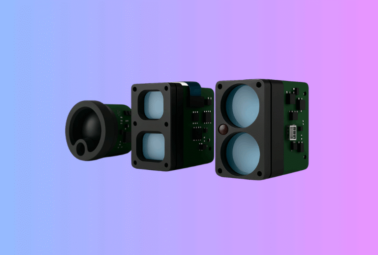
For many brands, a laser rangefinder module is the heart of their product: golf and hunting rangefinders, smart surveying tools, industrial sensors or autonomous vehicles. If that core fails in the field, the whole device fails. For B2B buyers, the question is no longer just “What range and accuracy can I get?” but “Will this module still be working in five to seven years?”
Table of Contents
ToggleLong-term reliability is not an abstract concept. It affects warranty cost, brand reputation, reseller confidence and even resale value of finished devices. In this article we look at how to design and select laser rangefinder modules with realistic MTBF, proper derating, and a clear path to multi-year lifetime in real environments. The perspective is that of a China-based OEM/ODM manufacturer supplying configurable laser rangefinder modules and complete device designs.
1. Why long-term reliability matters in rangefinder-based products
In early-stage projects, engineering teams tend to focus on hitting key specs: maximum range, measurement speed, size and battery life. Reliability questions often come later—sometimes too late, when unexpected failures emerge in field use.
For B2B brands, the consequences include:
- higher warranty and RMA costs as units fail after a season or two;
- channel friction when distributors receive frequent complaints;
- damage to brand perception, especially in higher-priced “premium” segments;
- unexpected redesigns because a weak component was pushed too hard.
A 5–7 year lifetime design, even for consumer-facing products like golf or hunting rangefinders, changes the conversation. Instead of chasing marginal performance at all costs, you intentionally operate components below their limits and verify behaviour in realistic stress conditions. That is what reliability engineering is about.
2. What MTBF really means for laser rangefinder modules
MTBF (Mean Time Between Failures) is often used as a shorthand for reliability, but it is frequently misunderstood. It is not a guarantee that a module will run for X hours; rather, it is a statistical measure derived from component failure rates, accelerated tests or field data.
For a laser rangefinder module, MTBF is influenced by:
- the reliability of individual components (laser diode, detector, MCU, power ICs);
- environmental stresses (temperature, humidity, vibration);
- operating profile (pulse repetition frequency, duty cycle, on/off cycles).
Two modules with identical schematics can have very different real-world MTBF if one is driven close to maximum ratings in a hot, humid environment and the other is operated gently in a controlled climate.
For OEM buyers, the key questions are:
- How was the MTBF estimated (calculated from parts, measured in HALT/HASS, or based on field returns)?
- Under what assumptions of temperature, duty cycle and environment?
- Is there derating built into the design, or is the module operating near its limits?
A serious manufacturer will be transparent about these assumptions and help you map them to your use cases.
3. Derating: using components gently to extend life
Derating means deliberately operating components at less than their maximum rated stress—voltage, current, temperature or mechanical load—to improve lifetime and reduce failure risk.
In a laser rangefinder module, derating typically touches:
- Laser diode current: running pulses at a fraction of maximum drive current, especially in average-power terms.
- Power devices and capacitors: choosing voltage and temperature ratings with comfortable margins.
- Connectors and cables: not exceeding specified current or mechanical strain.
A simple example: if a laser diode is rated for 100 A peak at a given pulse width, a derated design might drive it at 60–70 A and limit PRF. That may sacrifice a little maximum range on white targets, but greatly extends expected lifetime, especially at high ambient temperatures.
The table below gives a conceptual comparison between “pushed” and “derated” design philosophies.
| Aspect | Aggressive Design | Derated Design |
|---|---|---|
| Laser drive | Close to maximum current and PRF | Margin on current and PRF, adjusted for temperature |
| Capacitors | Voltage rating near operating voltage | 1.5–2× voltage margin, long-life series |
| Thermal budget | High internal temperature acceptable | PCB, housing and firmware tuned to keep junction temps low |
| Expected field life | 1–3 seasons typical | 5–7 years under specified conditions |
For brands that plan premium lines or industrial variants, the derated approach offers more predictable total cost of ownership, even if headline range specs are slightly more conservative.
4. Environmental stresses: temperature, humidity, shock and vibration
Real products rarely enjoy perfect lab conditions. They sit in car trunks, on construction sites, in hunting blinds or on moving vehicles. Each environment brings specific stressors.
4.1 Temperature cycling
Repeated hot/cold cycles cause thermal expansion and contraction of PCBs, solder joints and optical mounts. Over time, this can:
- crack solder joints or vias;
- loosen mechanical fasteners;
- shift optical alignment, changing calibration.
Modules designed for 5–7 year life are tested with temperature cycling and design features such as flexible PCB regions, strain relief, and mounting methods that avoid concentrating stress.
4.2 Humidity and condensation
Moisture ingress is a silent killer. Humidity and condensation can:
- corrode pads and connector contacts;
- change dielectric properties, affecting high-impedance circuits;
- fog internal optics, reducing signal strength.
Using sealed housings, conformal coatings and suitable gaskets reduces risk, but you must also consider drying behaviour. For example, a rangefinder used in rain and then stored in a warm case should be able to vent moisture or withstand elevated humidity internally without damage.
4.3 Mechanical shock and vibration
Drops, recoil (for weapon-mounted devices) and constant vibration (on vehicles) stress both mechanical and electronic elements. Over time, they can:
- loosen screws and lens barrels;
- crack brittle solder joints;
- misalign optics, changing the relationship between aim point and beam.
Robust mounting schemes, thread-locking methods and shock-absorbing elements all contribute to lifetime, but they must be validated with drop tests and vibration profiles that reflect real usage.
The table below summarises typical stress factors and associated failure modes.
| Stress Factor | Typical Sources | Common Failure Modes |
|---|---|---|
| Temperature cycling | Day/night exposure, hot car, cold storage | Solder fatigue, alignment drift |
| High humidity | Rain, fog, monsoon, storage in damp cases | Corrosion, fogged optics, leakage |
| Shock | Drops, recoil, accidental impacts | Cracked boards, broken lenses, intermittent connections |
| Vibration | Vehicle mounting, machinery | Connector fretting, screw loosening, optical rotation |
Designing for reliability means recognising which of these dominate in your target market and working with your OEM partner to test accordingly.
5. PRF, duty cycle and optical lifetime
Laser diodes do not live forever. Each pulse contributes slightly to degradation of the active region, especially at elevated temperatures. Over millions or billions of pulses, output power declines.
Two modules can use the same diode but experience different aging curves depending on:
- pulse repetition frequency (PRF),
- pulse width and current,
- thermal management.
Golf rangefinders, for example, may spend most of their life in short bursts of measurement, with plenty of cool-down time. A rangefinder module used in a vehicle’s collision-avoidance system might operate at high PRF continuously, significantly increasing stress.
Lifetime-oriented design therefore includes:
- defining realistic PRF limits for continuous operation;
- using firmware to adapt PRF based on temperature;
- setting conservative maximum ranges rather than chasing every metre with higher currents.
When you discuss lifetime with a module supplier, it is good to ask for duty-cycle recommendations and any internal data on power degradation over time under accelerated tests.
6. Designing for a 5–7 year field life
A 5–7 year lifetime goal translates into concrete design and process decisions.
6.1 Component selection and derating rules
At PCB level, choose components with:
- appropriate voltage and temperature ratings (for example, electrolytics rated 105°C or higher);
- stable packages and terminations suited to your assembly process;
- suppliers with long-term availability plans.
Apply derating guidelines—often 50–70% of maximum ratings—for critical parts such as power FETs, laser drivers and resistors that see high dissipation.
6.2 Thermal design and housing
Use simulation and testing to understand hot spots inside the module and finished device. Simple steps like:
- thermal vias under power ICs;
- conductive paths to the housing;
- avoiding heat sources behind the detector;
can significantly reduce internal junction temperatures. In products that also include thermal imaging, choosing compatible layouts—like those used in Gemin’s combined imaging and thermal camera module projects—prevents mutual heating between subsystems.
6.3 Firmware safeguards
Firmware is an ally for reliability. It can:
- throttle measurement rate when internal temperature is high;
- detect abnormal current draw or signal patterns and log warnings;
- limit “hidden” engineering modes that bypass safety margins.
By designing these safeguards up front, you avoid field situations where heavy users unknowingly stress the hardware beyond its lifetime assumptions.
7. Reliability testing: from HALT to production burn-in
Numbers on a spreadsheet are not enough. To gain confidence in lifetime, you need structured testing.
7.1 HALT (Highly Accelerated Life Test)
HALT subjects early prototypes to extreme combinations of temperature, vibration and electrical stress. The intent is not to simulate real life exactly, but to find weak links quickly: components that fail early, mechanical structures that resonate, or software that misbehaves under edge conditions. Lessons learned here feed back into design changes.
7.2 Qualification testing
Once the design stabilises, you perform qualification tests that are closer to actual conditions:
- temperature cycling over the specified range;
- humidity and salt-fog exposure, if relevant;
- drop, recoil and vibration tests;
- long-term PRF operation at elevated temperature.
You do not need to run prototypes for seven years; instead, you use accelerated aging and statistical models to extrapolate failure rates.
7.3 Production burn-in and sampling
In mass production, a modest burn-in—operating modules for some hours at elevated temperature—is often enough to weed out early “infant mortality” failures. Additional sampling from each batch can be subjected to more aggressive tests to verify that reliability remains consistent over time and across component lots.
An OEM partner that already applies such processes to its golf, hunting and industrial rangefinders—and documents them in its rangefinder module integration programmes—gives you a more solid basis for your own reliability claims.
8. Turning reliability into B2B value: warranty and TCO
Designing for reliability is only half the story; you also need to express it in terms that purchasing and management care about.
A 5–7 year lifetime design lets you:
- offer longer, differentiated warranties on premium products;
- reduce RMA handling costs and inventory of spare units;
- model the total cost of ownership more accurately for B2B customers.
For example, a hunting brand that positions itself as a durable choice can support that message with:
- clear statements about environmental testing and derating;
- stable behaviour of its golf and hunting rangefinder modules over several seasons;
- documented refinements between generations, rather than constant emergency redesigns.
Industrial users—such as those embedding modules into robotics or safety systems—often require explicit lifetime statements in their own datasheets. Designing at module level with MTBF and derating in mind makes it possible to support those statements with real engineering, not just marketing.
9. How Gemin Optics approaches long-term reliability in LRF modules
As an OEM/ODM laser rangefinder module manufacturer, Gemin Optics integrates reliability thinking into both module and finished-device programmes. Key elements include:
- Derated designs that favour stable long-term behaviour over aggressive headline specs, with clear derating rules for current, voltage and temperature.
- Environmental and lifetime testing across representative use cases—golf, hunting, surveying and industrial—so the same core platform can be tuned reliably for different markets.
- Traceability and data: batch-level tracking of components, test results and firmware versions to support field analysis and continuous improvement.
- Integration support for customers who want to hit specific lifetime targets, translating MTBF and derating assumptions into practical design choices at device level.
Because Gemin also supplies thermal and imaging solutions, reliability lessons learned in one segment (for example, sealing and coating for harsh climates) can be shared across others, giving OEM customers a broader knowledge base to draw from.
CTA – Design Your Next Laser Rangefinder Module for a 5–7 Year Lifetime
Chasing maximum range and flashy specs is easy; designing a laser rangefinder module that quietly delivers accurate measurements year after year is harder—and far more valuable for serious B2B buyers. By understanding MTBF, applying thoughtful derating, and validating behaviour under real environmental stresses, you can offer products that protect both your margin and your reputation.
If you are planning a new rangefinder line or reviewing the reliability of an existing design, consider building on a derated, well-characterised module platform. You can explore Gemin Optics’ configurable laser rangefinder modules and reliability-focused rangefinder module integration services, then work with our engineering team to define a 5–7 year lifetime strategy that matches your brand positioning and customer expectations.