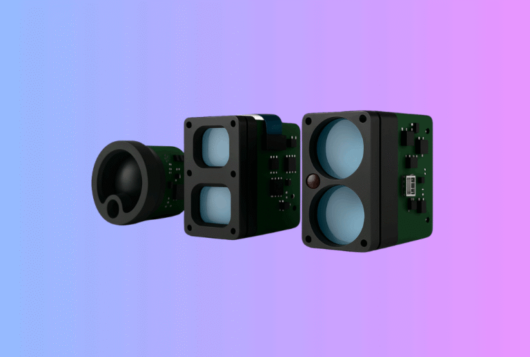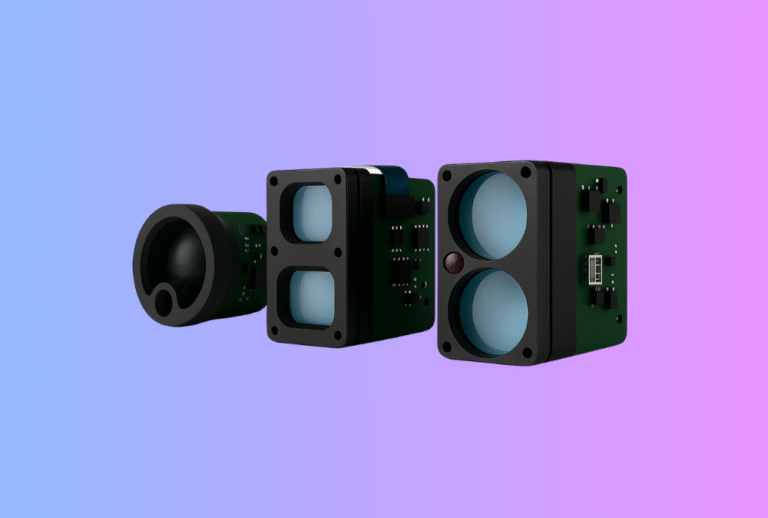
For many brands, the laser rangefinder module is a small part of the total BOM but a big part of EMC and ESD headaches. The module sits close to high-speed drivers, long cables, batteries and displays. When something goes wrong, it shows up as CE/FCC test failures, random resets in the field, or “mystery distances” when a user touches the housing on a dry winter day.
Table of Contents
ToggleFor OEM buyers and integrators, ignoring EMC and ESD until the end of a project is a guaranteed way to lose time and money. A better approach is to treat the rangefinder as an RF and ESD-sensitive sub-system from day one and design housing, layout and cabling around that reality.
This article explains how to do that. It draws on practical experience from Gemin Optics as a China-based laser rangefinder module manufacturer and OEM/ODM supplier, supporting applications from consumer golf rangefinder modules to industrial sensors and robotics.
1. Why EMC & ESD matter so much for laser rangefinders
Electromagnetic compatibility (EMC) and electrostatic discharge (ESD) are not just lab test terms. They influence real-world behaviour every day:
- A customer presses “measure” near a radio or inverter and the device freezes.
- A hunter touches a metal eyecup in cold, dry air and the rangefinder resets.
- A warehouse AGV drives past a VFD cabinet and loses its distance readings.
From a B2B perspective, these problems mean warranty claims, angry distributors and sometimes product recalls. Passing CE/FCC once is not enough; you need a design that behaves robustly across different markets and environments.
Laser rangefinder modules are especially sensitive because they combine:
- fast, high-current laser drive pulses (a source of EMI);
- high-impedance analog front ends for the receiver (susceptible to noise);
- interfaces that run outside the housing (UART, RS485, CAN, USB);
- user contact points like buttons, eyepieces and tripod mounts.
Good EMC/ESD design treats the module, PCB, housing and cables as one system, not separate pieces.
2. EMC & ESD basics for rangefinder designers
2.1 EMC in practice
EMC is about two things:
- Emissions – your product should not disturb radios, Wi-Fi, other devices or itself.
- Immunity – your product should keep working when nearby equipment emits noise.
For laser rangefinders, key tests under CE/FCC typically include radiated and conducted emissions, radiated RF immunity, EFT/burst, surge (for mains-powered gear) and sometimes conducted immunity on signal lines.
2.2 ESD in practice
ESD is a sudden discharge of static electricity, usually from a charged person to the device or between different parts of the device itself. Standards such as IEC 61000-4-2 define both contact discharge (through direct metal touch points) and air discharge (through gaps).
On a rangefinder, ESD often hits:
- metal trim rings, eyecups or tripod threads;
- buttons and keypad areas;
- connectors (USB, charging ports, external triggers).
Proper protection prevents these events from resetting the MCU, corrupting measurement data or damaging components.
3. Typical EMC/ESD failure modes in laser rangefinder modules
Understanding how failures show up helps you design countermeasures. Common symptoms include:
- Random resets when the laser fires at high PRF or when other electronics switch.
- Measurement spikes at certain distances or in specific orientations.
- USB or UART communication errors when radios or mobile phones are near.
- Permanent damage after strong ESD events, often at connectors.
Root causes are usually found in a few areas: poor grounding, lack of segregation between noisy and sensitive circuits, unprotected external lines, or housings that unintentionally couple RF energy into the module.
4. PCB layout and grounding around the module
If you design the carrier board or main PCB that hosts the module, layout is your first line of defence.
Keep current loops small. Laser driver paths, battery connections and any inductive components should form tight loops with minimal area; otherwise they radiate like antennas. Route high-di/dt traces close to their return paths and avoid running them under sensitive analog inputs.
Use solid ground planes instead of narrow traces. A continuous ground plane under the module and high-speed sections provides a stable reference and reduces impedance. Where you must split ground (for example analog vs digital), do it carefully and reconnect at a single point, not with long “bridge” traces.
Place decoupling capacitors as close as possible to IC power pins, especially for the laser driver and receiver front end. Combine small ceramics (e.g. 100 nF) with larger values (1–10 µF) to handle both fast and slower transients.
For modules that connect via board-to-board headers, follow any layout guidelines from the module vendor. In Gemin’s OEM projects, for example, recommended footprints and keep-out zones around laser rangefinder modules are part of the integration package to avoid crosstalk and ensure clean returns.
5. Protecting interfaces: UART, CAN, USB and trigger lines
External interfaces are convenient entry and exit points for noise and ESD. Design them with protection in mind from the start.
On UART and RS485/RS232 lines, use series resistors and common-mode chokes where appropriate. TVS diodes sized for the signal voltage help clamp ESD events before they reach transceivers or MCU pins. Place these components near the connector, not near the MCU.
For CAN bus, follow automotive or industrial reference designs: controlled impedance, terminations at both ends, and common-mode chokes plus TVS arrays sized for automotive-class ESD levels.
USB is especially sensitive. Differential impedance control, careful routing, and dedicated USB protection ICs are recommended. Avoid stubs and route D+/D– pairs together with matched length.
Trigger or sync lines used for measurement timing should avoid long unshielded runs. If they must travel far, treat them like any other digital interface with proper protection and return paths.
The following table summarises typical protection strategies.
| Interface | Main Risks | Common Protections |
|---|---|---|
| UART / RS232 | ESD, burst, RF pickup | Series resistors, small RC filters, TVS diodes |
| RS485 | Common-mode noise, ESD | TVS arrays, common-mode choke, proper termination |
| CAN | ESD, surges in vehicles | CAN-specific TVS, choke, robust transceiver, good grounding |
| USB | ESD, RF, high-speed reflections | USB TVS, controlled impedance, short matched pairs |
By treating each connector as a little EMC/ESD project, you avoid “mystery” system failures later.
6. Shielding, enclosure design and mechanical paths
Even with a clean PCB, the housing can make or break EMC performance. Plastic cases, metal trims, screws and shields all influence how currents flow during RF and ESD events.
Decide early whether the module will sit inside a shielded cavity (for example, a metal sub-chassis or can) or rely on the main housing for shielding. A simple metal shield over the laser driver and receiver section can greatly cut radiated emissions and protect the front end from external fields. Make sure the shield has a low-impedance connection to ground, not just a single long tab.
If your housing has metal decorative parts (bezels, buttons, tripod threads), treat them as intentional ESD entry points. Provide dedicated discharge paths from these parts to system ground, often via resistors or direct bonding, so discharges bypass sensitive signal traces.
Pay attention to seams and joints. ESD often jumps across small gaps; consider overlapping plastic parts or conductive gaskets where necessary. For waterproof designs, the gasket must work for both sealing and, in some cases, electromagnetic isolation.
In multi-sensor products that combine a rangefinder with a thermal camera module, mechanical design must also prevent one subsystem’s shielding from creating unexpected resonances or cavity antennas that hurt the other. Coordinated mechanical and EMC design is essential.
7. Power supply design and conducted noise
Power supplies inject noise into every part of the system if not controlled. Laser drivers draw sharp current pulses; DC-DC converters switch at hundreds of kHz or MHz; USB charging can introduce its own ripple.
Choose switching regulators with good EMI performance and follow their layout recommendations closely. Keep switch nodes as small as possible and route noisy loops away from the rangefinder’s analog front end. Snubbers and additional LC filters may be needed if conducted emissions are high.
Add local regulation for the rangefinder module when feasible. A clean LDO fed by a pre-filtered rail can isolate the module from upstream switching noise. Separate analog and digital power domains, each with appropriate filtering, reduce coupling.
Battery-powered products benefit from careful routing of high-current paths. The battery–switch–laser driver loop should be compact and well separated from precision analog circuits.
8. Planning your CE/FCC and ESD test strategy
A smart EMC plan starts long before the certification lab.
During development, schedule pre-compliance testing in a smaller chamber or with near-field probes. This helps you see problem frequencies early and adjust layout, shielding or firmware (for example, spread-spectrum switching) before hardware is frozen.
When you reach formal testing, discuss with your lab:
- applicable standards (EN 55032/47, FCC Part 15, IEC 61000-4-2/3/4 etc.);
- worst-case operating modes (maximum laser PRF, all radios on, charging);
- cable configurations and orientations.
For ESD, practice good test discipline: hit all likely contact points, increase voltage in steps, and observe not just whether the device resets but also whether its measurement performance changes. Logging distance readings during tests helps catch subtle problems.
If you work with an OEM partner like Gemin Optics, many issues can be solved at module level. Modules used in our laser rangefinder module integration projects are pre-examined for emissions and immunity, giving you a more solid starting point for the whole device.
9. Working with a China OEM manufacturer on EMC-ready modules
When sourcing modules from a China-based manufacturer, it is worth asking specific EMC/ESD questions rather than treating them as black boxes. For example:
- Have the modules been measured for radiated and conducted emissions on a reference board?
- What protection is already built in for supply lines and I/Os?
- Are reference PCB designs and layout guidelines available?
- Can the module supplier support CE/FCC documentation with test summaries?
A mature OEM partner will offer more than a datasheet. Gemin Optics, for instance, provides:
- reference designs for laser rangefinder module carriers that have passed EMC pre-tests;
- recommendations for shielding, grounding and cable routing in common form factors;
- support during your own CE/FCC and ESD campaigns, helping interpret test results and propose fixes.
This collaboration can be the difference between “one quick test pass” and months of trial-and-error redesigns.
10. CTA – Build EMC & ESD Compliance into Your Next Laser Rangefinder Module Design
EMC and ESD issues are rarely visible in CAD, yet they are often the biggest source of last-minute delays and hidden warranty costs. By designing your laser rangefinder module integration with emissions, immunity and ESD paths in mind—from PCB layout to housing and cabling—you can approach CE/FCC testing with confidence instead of fear.
If you are planning a new rangefinder-based product or reviewing an existing design that struggled in the lab, consider partnering with a China OEM that treats EMC as part of the platform, not an afterthought. Gemin Optics offers configurable laser rangefinder modules and practical rangefinder module integration support to help you pass CE/FCC and ESD tests without painful redesigns.