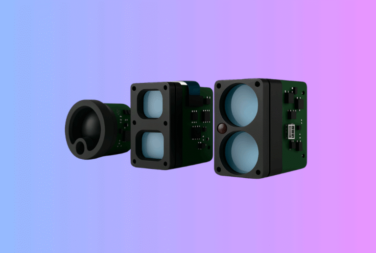
When an OEM team evaluates a new sensor platform, the Thermal Camera Module Development Kit and the Laser Rangefinder Module Evaluation Kit are often their first real contact with the technology. Long before purchasing volume hardware, buyers judge a supplier by how fast they can power up the kit, get useful data on the screen, and answer basic integration questions.
Table of Contents
ToggleA well-designed development kit does far more than blink LEDs and show a demo image. It helps embedded engineers, test engineers, and product managers all answer the same question: “Can this platform be integrated into our product family with acceptable risk, cost and schedule?”
In this article, we break down what a good OEM kit should contain, what different stakeholders expect from it, and how Gemin Optics designs evaluation platforms around our thermal imaging modules and laser rangefinder modules to shorten the decision cycle for B2B customers.
1. Why development kits matter for thermal and LRF projects
Thermal camera modules and laser rangefinder modules sit at the heart of larger systems—rifle scopes, handheld monoculars, UAV gimbals, industrial monitoring systems and more. When something goes wrong later in the project, it is often traced back to assumptions made during early evaluation:
- The host processor could not handle the actual video bandwidth.
- The rangefinder’s safety class and divergence were not compatible with enclosure design.
- Latency between sensor, processing pipeline and display exceeded what the UX team expected.
A solid Thermal Camera Module Development Kit or Laser Rangefinder Module Evaluation Kit reduces these risks by allowing the OEM to evaluate:
- Interface compatibility (MIPI, LVDS, parallel CMOS, UART, CAN, Ethernet, USB).
- Power and thermal behaviour in realistic scenarios.
- Optics and FOV suitability for the intended application.
- Integration of SDKs into existing software architectures.
The better the kit, the sooner a buyer can move from marketing discussions to hard technical facts.
2. Core objectives of a Thermal Camera Module Development Kit
A development kit is not a finished product. It is a laboratory tool designed to expose the capabilities and limits of a thermal core with minimal friction. In practice, a strong kit should support three main objectives.
2.1 Fast bring-up and basic image validation
The first task for any engineer receiving a kit is simple: “Can I power this on and see a stable image without reading a 200-page manual?”
To enable this, the kit should ship with:
- A pre-assembled evaluation board with all critical regulators, clock sources and protections.
- Clearly labelled connectors for power, data and I/O.
- A desktop GUI that automatically recognises the board, displays live video, and allows basic control (NUC, palettes, AGC modes, digital zoom).
Within minutes, the engineer should be able to confirm:
- image quality and NETD in typical ambient conditions,
- responsiveness of the AGC and NUC routines,
- stability of the video stream over the chosen interface.
This “first impression” often sets the tone for the whole project.
2.2 Interface and host-system integration
After initial bring-up, the next step is to integrate the core with the OEM’s own electronics. A good Thermal Camera Module Development Kit therefore exposes all relevant interfaces, not just USB:
- primary video/output path (MIPI, LVDS or parallel bus);
- control channels (I²C, SPI, UART, Ethernet);
- GPIO lines for trigger, NUC, FFC flag, sync signals;
- optional interfaces such as temperature probe inputs or lens control.
The evaluation board should include test points and headers so engineers can:
- monitor signalling with oscilloscopes and logic analysers,
- measure real current consumption by rail,
- inject external triggers or sync signals,
- prototype custom lens-control boards or focus mechanisms.
A comprehensive SDK and API documentation, with examples for common platforms (e.g. STM32, NXP i.MX, Xilinx/AMD, NVIDIA Jetson), lets firmware teams quickly integrate the module into their own pipeline or into an existing industrial thermal camera platform.
2.3 Temperature measurement and calibration exploration
For temperature-measuring applications—such as industrial thermal camera online systems or BESS monitoring—customers must validate measurement accuracy and drift behaviour. A good kit therefore supports:
- multiple temperature ranges and calibration tables,
- emissivity adjustment in the GUI and API,
- region-of-interest measurement, isotherm overlays,
- access to raw or linearised data for custom analytics.
The kit does not replace a blackbody calibration bench, but it should expose enough controls and data to let OEMs test their own compensation algorithms or verify performance against their internal standards.
3. What belongs in a complete Laser Rangefinder Module Evaluation Kit
Laser rangefinder projects face their own set of challenges: eye-safety, beam divergence, mechanical alignment and application-specific filtering logic. A Laser Rangefinder Module Evaluation Kit needs to make these factors visible early.
3.1 Opto-mechanical fixtures and safety
Good practice is to include:
- a mechanical fixture or bracket that holds the module at a fixed orientation, with clear axes for pitch and yaw;
- an adjustable sight or alignment aid (simple optical sight, mechanical bore-sight, or rail mount) to test repeatability;
- safety labels and clear documentation of IEC 60825-1 or FDA Laser Notice 56 classification;
- recommended separation distances and safe test procedures.
For indoor tests, simple attenuation filters or reference targets help engineers practise without exceeding range or safety limits.
3.2 GUI and control functions
A robust evaluation GUI for the LRF module should provide:
- continuous and single-shot modes with PRF readouts;
- display of raw and filtered distance, signal strength and error codes;
- adjustable filters for minimum/maximum range, reflectivity thresholds and multi-target handling;
- logging to file with timestamps for later analysis.
For integrators building golf rangefinders, thermal scopes or smart surveying tools, this GUI becomes the first place to experiment with application-level logic—such as near-target priority for brushy hunting scenes or slope compensation for golfing.
3.3 Interface and protocol access
As with thermal cores, the LRF evaluation board should expose both data and control interfaces:
- UART / CAN / SPI / USB options,
- full protocol documentation with command and response formats,
- checksum or CRC schemes,
- examples in C/C++, Python or other common languages.
This allows OEMs to connect the module directly to their main board, rather than treating the evaluation kit as a black box.
4. Hardware contents: what should physically be in the box?
A practical development kit for thermal or LRF modules typically includes the following hardware elements:
- Evaluation board pre-soldered with the module and all essential support circuitry.
- Standardised cabling, including USB, Ethernet or flat-flex cables, to connect to PCs and host systems.
- Power supply compatible with regional mains voltages, or at least clear guidance on safe DC input ranges.
- Adapters or fixtures for tripods, rails or simple mounting, allowing easy alignment tests.
- Optional accessories such as focus tools, alignment plates, or test targets that simplify bench validation.
From an OEM’s perspective, the key is that nothing “trivial” blocks progress. Engineers should not have to spend days soldering their own breakout boards or hunting for the correct FFC pitch.
5. Software, documentation and examples: the other half of the kit
Hardware is only half the story. For complex imaging systems, what determines real usability is the software and documentation layer.
5.1 GUI tools built for engineers
A good GUI is not just marketing graphics. It should:
- expose low-level parameters (gain, offset, AGC curve selection, noise filters) as well as high-level modes;
- visualise key diagnostics: sensor temperature, supply voltages, frame rate, network status;
- provide record-and-playback functions for sequence analysis;
- support both live control and offline configuration export (for embedding parameters into firmware).
For some projects, direct access to configuration files or command scripts is also important, enabling reproducible tests across sites.
5.2 SDKs and sample code
To integrate thermal and LRF modules into different host platforms, engineers need clear, concise examples. A solid kit offers:
- well-structured SDKs for Windows and Linux, and optionally for embedded RTOS targets;
- minimal, readable sample projects showing:
- basic image and distance acquisition;
- configuration of frame rate, modes and ROI;
- error handling and reconnection logic;
- build instructions and dependency lists for each environment.
For OEMs planning to integrate cores into their own OEM/ODM solutions, this code becomes a reference for their internal developers and external partners.
5.3 Clear documentation
Documentation is often undervalued, yet it is the primary interface between the supplier and the customer’s engineering team. A complete kit should include:
- a concise getting-started guide that walks through hardware setup, driver installation and first image/range measurement;
- a hardware reference manual covering pinouts, power rails, timing diagrams, mechanical dimensions and environmental specifications;
- a software reference describing all API functions, parameters, and typical call sequences;
- application notes for popular use cases (hunting scope, industrial fixed camera, mobile robot, survey tool).
For many buyers, the quality of documentation is a direct proxy for the maturity of the engineering organisation behind the modules.
6. Different stakeholders, different expectations from the EVK
A good development kit serves more than one audience inside the OEM. Each role looks at the kit through a different lens.
6.1 Embedded and system engineers
Embedded engineers focus on interfaces and performance. They need to know:
- Can the host processor handle the data throughput at the required frame rate?
- Does the module behave predictably when power is cycled, when clocks drift, or when network connections are interrupted?
- How easy is it to integrate the SDK into existing middleware and UI layers?
For them, low-level control, logging and diagnostics are more valuable than a polished demo.
6.2 Test and validation engineers
Test teams use the kit to establish objective criteria for future production testing. They will:
- measure NETD, SNR and non-uniformity across temperatures;
- check ranging accuracy against known targets at multiple distances;
- evaluate repeatability after vibration or temperature cycling;
- define pass/fail limits and test sequences.
They expect the kit to provide stable, repeatable behaviour and access to raw data, not just processed outputs.
6.3 Product managers and procurement
Product and sourcing teams view the development kit as a risk-reduction tool. Using simple setups and GUI views, they want to confirm:
- that image and range performance meets market expectations for their price segment;
- that configuration flexibility exists to create multiple SKUs from one core;
- that the supplier’s technical support is responsive and competent.
A well-organised kit and prompt assistance from the vendor’s application engineers give them confidence to move forward with tooling, certification planning and launch timelines.
7. How good development kits shorten evaluation cycles
From the OEM side, a common frustration is losing weeks on avoidable friction: missing cables, ambiguous pinouts, incomplete drivers or unstable sample software. A strong Thermal Camera Module Development Kit and Laser Rangefinder Module Evaluation Kit address this by:
- reducing bring-up time from days to hours;
- making it easy to run standardised scenarios across multiple internal stakeholders;
- enabling early end-to-end tests with the OEM’s own enclosure, optics or host electronics;
- providing clear, supportable baselines for future design reviews.
When the evaluation kit is well designed, the focus quickly shifts from “Can we make this run?” to “How do we shape a competitive product line around this core?” That is the point where both supplier and OEM start creating real value.
8. What Gemin Optics includes in its OEM evaluation platforms
At Gemin Optics, our evaluation kits are built around the same principles that guide our production modules and quality control processes. For both thermal imaging and laser rangefinding, we emphasise:
- Complete hardware packages – assembled evaluation boards, standard cables, compatible power solutions and basic fixtures, all tested before shipment.
- Cross-platform software tools – GUI applications and SDKs designed for quick bring-up and deep diagnostics, with sample code that engineers can adapt directly.
- Traceable configurations – firmware and configuration versions recorded per kit so that issues can be reproduced and analysed.
- Application-focused documentation – guides and notes that reflect real integration work in hunting optics, golfing devices, industrial monitoring and robotics.
- Responsive engineering support – direct contact with application engineers who understand both optics and system design, not only sales staff.
Our goal is for OEM partners to make a confident go/no-go decision on a platform within a predictable evaluation window, instead of struggling with ad-hoc experiments.
9. Getting the most value from a development kit
From the OEM side, a few practices can maximise the value of any evaluation kit:
- Define clear questions before the kit arrives. Decide which performance metrics, interfaces and environmental conditions must be validated in the first 4–6 weeks.
- Involve all stakeholders early. Let embedded, test and product teams each run their own scenarios using the same hardware.
- Document findings systematically. Use shared templates for recording image quality, range performance, thermal behaviour and software integration notes.
- Share structured feedback with the supplier. The best suppliers will use this data to refine their kits and, in some cases, their core designs.
When both sides treat the development kit as a joint engineering tool rather than a marketing sample, the path to stable, long-term cooperation becomes much clearer.
10. Working with Gemin Optics on development kits and OEM projects
A well-designed Thermal Camera Module Development Kit or Laser Rangefinder Module Evaluation Kit is often the first proof that a supplier can support you through a full product lifecycle—from early lab tests to scaled production and future platform updates.
Gemin Optics designs its kits to align with that goal: fast bring-up, deep access to interfaces and data, and documentation written for real engineering work. Combined with our modular thermal imaging modules, proven laser rangefinder modules, and flexible OEM/ODM solutions, they provide a practical starting point for new product families in hunting optics, surveying, robotics and industrial monitoring.
If you are planning a new thermal or LRF platform and want to evaluate cores with predictable risk and timeline, you can reach out via the Gemin Optics contact page to discuss a tailored development kit and evaluation plan with our engineering team.