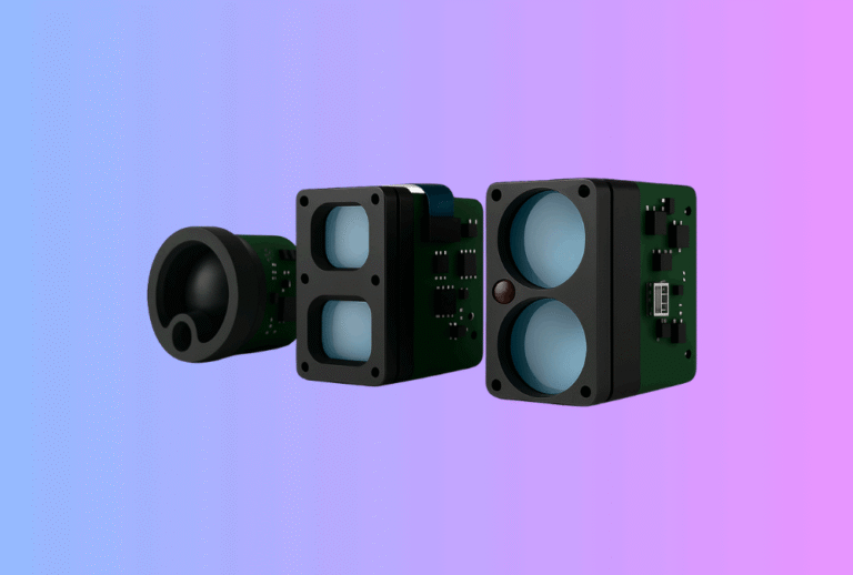
Laser Rangefinder Module DFM: Cost, Yield & Reliability
Lead: Moving a Laser Rangefinder Module from prototype to repeatable, profitable mass production isn’t just about “locking the BOM.” It’s a discipline: design-for-manufacturability (DFM), design-for-test (DFT), and design-for-reliability (DfR) working together to deliver stable yields, predictable costs, and field life that delights end-users.
Table of Contents
ToggleExecutive Summary
- Design choices dominate unit economics. Early decisions on emitter binning, APD bias control, beam shaping, and enclosure tolerances can swing gross margin by double digits through scrap, rework, and test time.
- Build for inspection—then for automation. Clear test points, fixture-friendly housings, and self-test telemetry reduce takt time and stabilize yield across shifts and factories.
- Reliability is a process, not a spec. Prove it with JEDEC-style qual (HTOL, temp-cycle, THB), production SPC, and targeted burn-in—not just a “pass/fail” at EVT.
- Safety & compliance are guardrails for DFM. IEC 60825-1 Class 1/1M limits define optical power budgets and aperture geometry; design to them from day one
- The business case is real. Independent analysts place the laser rangefinder market in the multi-billion-dollar range with ~7–15% CAGR through 2030–2034, rewarding OEMs that ramp robust modules quickly.
Explore our Laser Rangefinder Module options and sample programs.
Use Cases & Buyer Scenarios
UAV & mobile-robot integrators targeting repeatable builds
You need the same range performance on unit #1 and unit #10,000. DFM reduces optical alignment steps, simplifies boresight jigs, and ensures your pilot customers see identical results when you scale.
Outdoor optics brands preparing seasonal launches
For Thermal Rifle Scopes, native ranging adds real value, but volumes spike before hunting season. DFM makes sub-assemblies (emitter can, receiver can, optics barrel) kanban-ready so your final goods line rides the demand wave, not the other way round.
Industrial automation & security installers
In factories and on perimeters, downtime is cost. DFM + DFT give you field-replaceable modules with predictable calibration drift, shorter RMA cycles, and clean interfaces to PLCs and VMS backends. Pairing with a Thermal camera module enables fused detection + absolute distance for alarms that users trust.
Spec & Selection Guide
Below are the parameters that matter most for manufacturability, yield, and cost—not just for on-paper performance.
-
Wavelength (905 vs 1535/1550 nm). 905 nm supports Si-APDs and lower BOM; 1550 nm typically allows higher eye-safe peak power, boosting long-range SNR, but uses InGaAs detectors and may impact cost/lead time.
-
Beam divergence & diffuser strategy. Your safety aperture and diffuser tolerance stack determine both Class 1 margin and process capability (Cp/Cpk) at the beam profiler.
-
Pulse energy & PRF budgets. Define limits in firmware so line operators can’t “tune” performance beyond eye-safe power or thermal budgets.
-
APD bias & temperature control. Stable gain with NTC-based LUTs or closed-loop biasing slashes unit-to-unit variability and false alarms.
-
DFT hooks. Built-in photodiode taps or internal monitor channels allow automated optical power checks at ICT/FT—no human reading of meters.
-
Interconnects & IO. Choose connector families and pinouts that survive repeated fixture insertions; define UART/CAN/USB/MAVLink command coverage for factory test and field diagnostics.
Comparison: Specs with DFM implications
| Parameter | Typical Options | DFM Implication |
|---|---|---|
| Wavelength | 905 nm / 1550 nm | 1550 nm offers more eye-safe headroom but uses InGaAs APDs; plan sourcing and calibration accordingly. |
| Divergence | 0.5–3 mrad | Tighter beams need tighter lens/diffuser tolerances; model Cp/Cpk before PVT. |
| Pulse Energy | 1–20 µJ (pulsed) | Firmware limits + power telemetry reduce out-of-box failures and recalls. |
| Receiver | Si-APD / InGaAs-APD | Different bias, filters, and ESD controls; pick test sockets early. |
| Interfaces | UART / USB / CAN / MAVLink | Standardized test scripts minimize station variance and operator errors. |
| Enclosure | IP66/67 w/ window | Design window mounts for AQL checks; avoid stress that alters beam. |
Simple decision flow (DFM-first)
If target range ≤1.5 km and cost sensitivity high → 905 nm + Si-APD + wide Cpk on divergence.
Else if >2 km + public-facing demos or fusion with optics → 1550 nm + InGaAs APD + robust eye-safe guard bands.
If production will span multiple CMs → prefer connectorized sub-assemblies + fixture-friendly datum surfaces.
Always lock a test-mode command set before DVT → prevents “creative” tuning on the line.
Integration & Engineering Notes
Electrical & Interfaces (UART/USB/CAN/MAVLink/SDK)
-
Deterministic timestamps. Provide hardware timestamps so fixtures can validate timing jitter without high-end oscilloscopes.
-
Test-mode command set. Include: laser enable/disable, PRF/PW presets, power readback, return-histogram dump, APD bias report, temperature, and error flags.
-
Bed-of-nails access. Break out UART and supply rails on test pads; use pogo-pin footprints designed for ≥100k insertions.
-
EMC pre-compliance. Grounding/return-path control around the APD/TIA and shield cans reduces re-spin risk before CE/FCC scans.
Optics & Mechanics (mounting, alignment, recoil, sealing)
-
Datum design. Use orthogonal V-groove or dowel-pin datums so the same boresight jig works at EVT/DVT/PVT and in after-sales.
-
Alignment plan. Decide whether the emitter, receiver, or both are adjustable—ideally one is fixed by design, one is shimmed at FT.
-
Window & gasket stack. Pre-compress gaskets consistently (torque spec + thread locker) so beam doesn’t clip and divergence doesn’t drift with humidity.
-
Ruggedization. Validate shock/vibe (transport + drop + recoil) on the sub-assembly before final product tests; this is critical in clip-on optics like Thermal Clip-On Sight.
Firmware/ISP/Tuning (AGC, palettes, fusion, ranging algorithm)
-
Safe-state logic. Watchdogs force a “fail-dark” if power readback exceeds AEL or temperature exceeds threshold; log codes for RMA triage.
-
Self-calibration. On boot, capture a short calibration burst to normalize APD gain vs temperature; save to NVM with versioned schema.
-
Range quality metrics. Expose SNR, pulse width, and multi-return count—your fixtures (and customers) will use them to catch marginal assemblies.
-
Fusion UI. If your end product overlays range on thermal video (e.g., Thermal Monoculars or Thermal Binoculars), provide a normalized confidence bar so UX stays stable across firmware revs.
Testing & Validation (bench → field, acceptance criteria)
-
JEDEC-style qual: HTOL, Temperature Cycling, and THB are standard reliability screens to reveal early-life failures.
-
IPC acceptance: Build to IPC-A-610 Class 2/3 depending on your sector; it’s the most widely used visual acceptance standard for PCBAs.
-
Laser safety loop: Verify IEC 60825-1 Class 1/1M with safety aperture measurements and divergence maps at PVT and on every process change.
-
Field equivalence: Use golden targets (Lambertian + retroreflector), standardize distances (e.g., 100 m, 500 m, 1 km), and log FAR (false-alarm rate) at dusk/daylight.
Compliance, Export & Certifications
-
Eye safety: Design and label to IEC 60825-1 Class 1 (or 1M) and keep a documented safety case (test methods, instruments, personnel).
-
US FDA guidance: For US shipments, ensure your documentation aligns to FDA Laser Notice No. 56 (harmonization with IEC 60825-1).
-
EMC/EMI: CE/UKCA and FCC Part 15 radiated/conducted emissions; verify in pre-scan before booking final lab time.
-
RoHS/REACH: Maintain material declarations for optics, solders, adhesives, and cable jackets.
-
Export control: Long-range LRFs and fused thermal+LRF systems may fall under dual-use rules; screen destinations and end-use.
Business Model, MOQ & Lead Time (OEM/ODM)
-
Samples & NPI: EVT samples in 2–4 weeks (standard optics), custom divergence or window coatings in 4–6 weeks.
-
MOQ: 50–200 pcs for standard SKUs; 300+ for custom optics/housings.
-
Mass production: 6–10 weeks ARO after design freeze; add lead time for private-label artwork and compliance labels.
-
Bundles: Offer demo kits for outdoor optics families—e.g., pairing with Thermal Pistol Sights for compact demos.
A simple (and realistic) DFM ROI model
| Driver | Baseline | After DFM | Annual Volume | Impact |
|---|---|---|---|---|
| FT pass rate | 92% | 98% | 10,000 | +600 fewer reworks |
| Rework cost / unit | $18 | $12 | — | ~$3,600 saved |
| FT takt time | 180 s | 140 s | 10,000 | ~+444 labor-hrs saved |
| Scrap rate | 2.0% | 0.8% | 10,000 | 120 units saved |
| Unit COGS | $220 | $214 | 10,000 | ~$60k saved |
Assumptions: blended labor $25/h; conservative improvements typical of first DFM pass.
Pitfalls, Benchmarks & QA
Common mistakes to avoid
-
Treating safety as a paperwork step. Eye-safe limits set your optical and driver budgets; retrofits are expensive.
-
No golden-unit policy. Without master references at each station, fixtures “wander” and yields follow.
-
Tuning on the line. Let firmware guard PRF/PW and power; operators should not decide performance.
-
Skipping divergence metrology. Safety and range depend on it; buy or build a beam profiler early.
-
Loose APD bias control. Temperature drift creates false returns; lock the bias algorithm before DVT.
-
Under-specced windows/gaskets. Humidity and torque variance can clip beams or change divergence.
-
Late EMC attention. Shielding and return paths are cheap on the PCB, expensive in the anechoic chamber.
Benchmarking method (make it repeatable)
-
Quote distances (100 m/500 m/1 km) for Lambertian and retroreflector targets.
-
Report detection and false-alarm rate for clear sky vs haze.
-
Publish confidence / SNR thresholds used by firmware so buyers can reproduce.
FAQs
1) Why are 1550 nm modules often marketed as “easier” for eye safety?
Because 1550 nm sits outside the retina’s most sensitive band, Class 1 AEL allows higher peak powers—useful for long-range SNR. You still need proper optics, firmware guards, and certification.
2) Are InGaAs APDs really more expensive?
Yes—InGaAs detectors typically cost more than Si-APDs, though new designs are closing the gap and improving sensitivity. Plan sourcing early.
3) Which PCBA quality standard should we quote?
Most OEMs use IPC-A-610 Class 2 or 3 depending on sector and criticality; it’s the dominant acceptance standard for electronic assemblies.
4) What reliability tests catch the most early-life issues?
HTOL (high-temp operating life), Temperature Cycling, and THB (temp-humidity-bias) are common screens derived from JEDEC JESD-series methods.
5) Can you pre-calibrate modules at the factory?
Yes. We log divergence, power, and timing on each unit and can provide calibration data files per serial number for your end-of-line flashing.
6) How does the market outlook affect my launch?
Multiple analysts forecast healthy growth (≈7–15% CAGR), so being first to a stable DFM is a competitive advantage with distributors and tier-1 integrators.
7) Do you support fused products (thermal + LRF)?
Yes—our modules are designed to pair with thermal families (monoculars, binoculars, clip-ons) and expose telemetry to overlay range cleanly on thermal video.
Call-to-Action (CTA)
If you’re preparing an EVT/DVT build, we can review your optical stack, APD bias plan, and fixture concept and return a DFM/DFT scorecard in 5 business days—plus a sample plan for pilot customers. Start with our Laser Rangefinder Module lineup and tell us your range targets, optics constraints, and interfaces.