Laser Rangefinder Module Calibration: Factory-to-Field
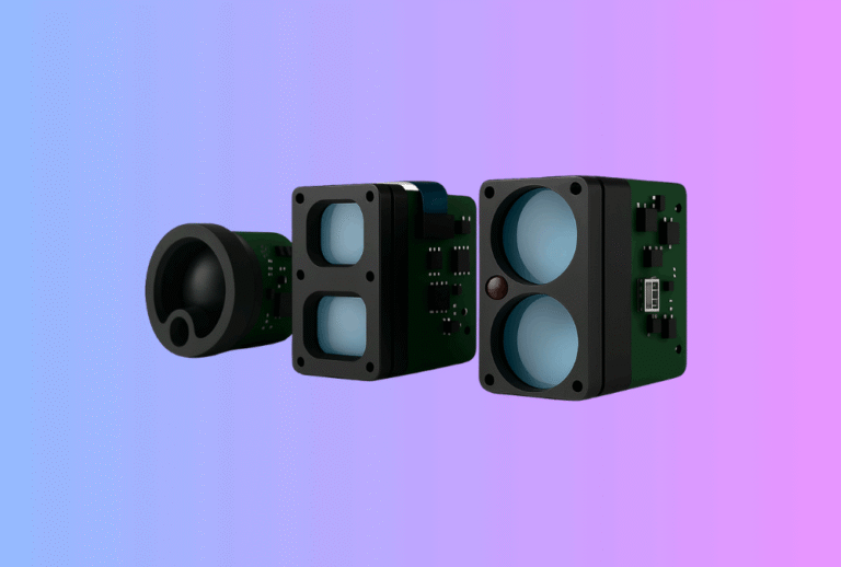
Lead: Accurate ranging doesn’t come from a datasheet—it’s earned in calibration. This guide shows OEM/ODM teams how to design a Laser Rangefinder Module with traceable factory calibration and a simple, repeatable field re-calibration flow, so units stay consistent from EVT to mass production to after-sales.
Table of Contents
ToggleExecutive Summary
- Calibrate what drifts: zero offset, scale/linearity, timing jitter, beam divergence, APD gain vs temperature, and boresight.
- Make calibration traceable: anchor your benches to SI-traceable standards (power/energy meters, distance artifacts) and require ISO/IEC 17025 certificates from partner labs.
- Close the loop in the field: provide a 2–5 minute re-check (golden target + self-test script) to catch shock, vibration, or window replacement effects. Tie it to your warranty.
- De-risk compliance early: maintain eye-safety margins (IEC 60825-1) in the same metrology loop you use for divergence and power.
- Yes, the business case is real: LRF demand continues to grow (multi-billion-dollar market; mid-single to low-teens CAGR), so shipping calibrated modules shortens pilots and speeds channel onboarding.
Use Cases & Buyer Scenarios
UAV mapping & robotics fleets (ROS2/MAVLink)
Fleet operators need unit-to-unit consistency for geo-tag accuracy and obstacle margins. Factory calibration normalizes offsets and timing; a field script re-checks after firmware updates or gimbal swaps. Pair with a Thermal camera module for fused detection + absolute range.
Outdoor optics brands (seasonal launches)
For Thermal Rifle Scopes, Thermal Monoculars, and Thermal Binoculars, pre-season re-checks prevent warranty spikes when devices sit in retail stock through temperature swings.
Industrial/security integrators
Fixed installations (perimeter towers, gates) need predictable drift and easy verification after window servicing. Provide a wall-chart range course or a tripod retroreflector for monthly checks.
Spec & Selection Guide
What your calibration actually controls—and why
-
Zero offset (system delay): removes constant timing bias from optics + electronics + firmware.
-
Scale / linearity: ensures distance is correct from near to far; often a two-point or multi-point fit.
-
Timing jitter: limits repeatability in high-PRF regimes; improves confidence metrics.
-
Divergence & power (eye-safety): verify emitted energy through the IEC safety aperture and map encircled energy; this protects Class 1 margins.
-
APD bias vs temperature: LUT or closed loop so gain is stable from cold start to hot soak.
-
Boresight: keep ranging axis aligned with the display/reticle or sensor axis for fusion.
Calibration comparison—factory vs field
| Item | Factory Method (traceable) | Field Check (minutes) | Typical Tolerance |
|---|---|---|---|
| Zero offset | Time-of-flight vs interferometric/known-distance fixture | Single fixed target at known D; script computes Δt | ±5–20 cm equiv. |
| Scale/linearity | Multi-distance rails: 10 m…1 km; polynomial fit | Two-point check: near/far targets | ≤0.5–1.0% full-scale |
| Timing jitter | Scope capture / histogram on bench | Scripted multi-shot at one distance | ≤0.5–1.0 ns RMS |
| Divergence & power (AEL) | Beam profiler + NIST-traceable power meter | Go/No-Go diffuser card + power readback | Per Class 1 budget |
| APD gain vs temp | Thermal chamber sweep; fit LUT | Cold-start + hot-soak quick test | ≤±1–2 dB var. |
| Boresight | Collimator/target wall; jigged datums | 25–100 m board alignment | ≤0.1–0.3° |
Decision flow (keep it simple)
If unit sees shock/vibration or window service → mandate a ≤5 min field check before next mission.
If long-range spec (>2 km) → add divergence map + power verification to every process change.
If fusion with thermal optics → always include boresight calibration & a reticle alignment step.
Integration & Engineering Notes
Electrical & Interfaces (UART/USB/CAN/MAVLink/SDK)
-
Time sync: expose hardware timestamps and PPS/TimeSync hooks for ROS2/MAVLink so logs can estimate real-world jitter.
-
Test commands:
laser_on/off, PRF/PW presets, energy readback, return histogram, APD bias, temperature, serial/firmware ID. -
Golden logs: fixtures store CSVs per serial; your RMA portal can validate a unit against its factory signature.
Optics & Mechanics (mounting, alignment, sealing)
-
Datum strategy: V-groove or dowel pins so the same jig works at EVT/DVT/PVT and after-sales.
-
Targets: matte Lambertian panels for scale checks; 3-corner retroreflectors for long-range sensitivity; alignment boards for boresight.
-
Windows & gaskets: torque spec and pre-compression repeatability—small gasket changes can alter divergence and zero.
Building clip-on or day-night stacks? Keep the ranging axis co-linear with the optical overlay in Thermal Clip-On Sight and handheld lines like Thermal Pistol Sights.
Firmware/ISP/Tuning (algorithms & NVM)
-
Self-cal: on boot, a short burst + temperature read refines the LUT; store versioned coefficients in NVM.
-
Quality metrics: output SNR, pulse width, multi-return count, and confidence so benches (and customers) can gate data.
-
Protection: “fail-dark” when energy readback exceeds limit or temp is high; logs keep auditors and tech support happy.
Testing & Validation (bench → field)
-
Metrology traceability: anchor power/energy meters and distance artifacts to SI via ISO/IEC 17025 labs or NIST services.
-
Environmental drift: temp cycling, humidity bias, and vibration per MIL-STD-810H to confirm calibration survives transport/use.
-
Acceptance criteria: define offset, linearity, jitter, divergence, and boresight gates; publish them in the CoC.
Compliance, Export & Certifications
-
Eye safety: maintain Class 1/1M per IEC 60825-1; your calibration loop should include safety-aperture power and divergence checks.
-
US shipments: FDA Laser Notice No. 56 recognizes conformance with IEC 60825-1 Ed.3 in lieu of certain domestic clauses—document it in your labeling file.
-
Calibration credibility: when using external labs, request ISO/IEC 17025 scope/certificates and uncertainty budgets.
-
Other marks: CE/FCC/UKCA for EMC; RoHS/REACH for materials (good practice to archive certificates alongside calibration records).
Business Model, MOQ & Lead Time (OEM/ODM)
-
Calibration kits: tripod retroreflector + matte board + quick-check script; ship with pilots.
-
Lead time: standard factory calibration benches in 2–4 weeks; custom long-range rails or diffuser maps in 4–8 weeks.
-
MOQ: 50–200 pcs for standard calibration; custom artifacts may set 300+ MOQ.
-
Documentation pack: per-serial CSVs (offset/scale/divergence), CoC, and Class 1 label proofs; these accelerate distributors’ onboarding of your Laser Rangefinder Module line.
Simple ROI for a field-check program
| Assumption | Baseline | With field check | Units/yr | Impact |
|---|---|---|---|---|
| RMA rate from mis-alignment | 2.0% | 0.8% | 5,000 | −60 RMAs |
| Tech time per RMA | 1.5 h | 1.5 h | — | ~−90 h |
| Avoided freight/handling | $45 | $45 | — | ~$2,700 |
| Customer downtime | 5 days | 2 days | — | ↑ NPS / retainment |
Pitfalls, Benchmarks & QA
Seven common mistakes
-
No traceability: meters and rails lack certificates—results won’t stand up in audits.
-
Cal only at room temp: units drift at −20 °C or 55 °C; include hot/cold points.
-
Skipping divergence maps: eye-safety and long-range SNR both depend on it.
-
Tuning on the line: operators “chase” range by changing PRF/PW—lock by firmware.
-
Boresight as an afterthought: especially painful on fused thermal products.
-
No golden-unit policy: stations wander without references and SPC.
-
Ignoring vibration: transport shock/vibe can move optics; verify per 810H.
Benchmarking method (repeatable & honest)
-
Build a range course: e.g., 25/50/100/250/500/1000 m markers with Lambertian and retroreflective targets.
-
Record offset, linearity error, jitter at each point, clear sky vs haze; include confidence thresholds and FAR.
-
For fused devices, add a boresight chart: pixel/reticle alignment error vs distance.
FAQs
1) Do we need an accredited lab for everything?
No—but for key artifacts (laser power meters, long rails), ISO/IEC 17025 traceability improves credibility and repeatability across CMs.
2) How often should field checks run?
At commissioning, after firmware/housing changes, and after any shock/vibe event; otherwise quarterly is typical for fleets.
3) What if our window or diffuser is replaced in service?
Run the quick-check script and a divergence Go/No-Go. If out of band, lock emission (“fail-dark”) until re-cal.
4) Can calibration fix poor optics?
No—calibration can remove offset/scale errors, but it can’t recover beam quality or SNR lost to bad components.
5) How is this different from production test?
Calibration writes coefficients to meet targets; test verifies results meet acceptance criteria. Do both.
6) Do we need to quote environmental standards?
Citing MIL-STD-810H methods for shock/vibe and temperature cycling is common and helps spec compliance in RFPs.
7) Why talk about IEC 60825-1 in a calibration article?
Because validating divergence and power in the same loop that sets range accuracy keeps your Class 1 margins intact.
Call-to-Action (CTA)
Planning EVT/DVT now? We can design your bench, supply calibration kits, and deliver a traceable coefficient pack per serial number—plus a 5-minute field check workflow for installers and distributors. Start with our Laser Rangefinder Module lineup and tell us your distances, interfaces, and environmental limits.