ROS 2 & MAVLink Time Sync for Laser Rangefinder Modules
Lead: If your Laser Rangefinder Module timestamps are off by a few milliseconds, fused perception and mapping can drift by meters. This integration-first guide shows OEM/ODM teams how to make an LRF speak fluent ROS 2 and MAVLink with hardware timestamps, PPS discipline, and deterministic bridges—so range, video, thermal, and IMU all land in the same clock domain.
Table of Contents
ToggleExecutive Summary
- Use event time, not publish time. LRF messages must carry the capture time (when the pulse/return pair is measured), not the moment the driver publishes. In ROS, that’s the
Header.stampsemantics. - Pick a clock strategy and stick to it. For single-machine tests, system time works; for fleets and UAVs, use GNSS PPS + TIMESYNC (MAVLink) or PTP (IEEE 1588) for sub-ms to sub-µs alignment.
- Bridge autopilot and ROS 2 deterministically. Implement MAVLink
TIMESYNCon the companion side and map to ROS 2Header.stamp; enable/clockwhenever simulation or log-replay is used (use_sim_time). - Engineer QA around time. Test offset, jitter, and drift on a bench with PPS or a PTP grandmaster; assert thresholds in CI and end-of-line tests.
- Design for fusion. Expose confidence/SNR, multi-return counts, and hardware timestamps so downstream fusion (thermal + LRF + IMU) stays consistent across SKUs.
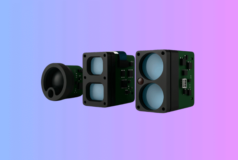
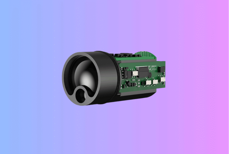
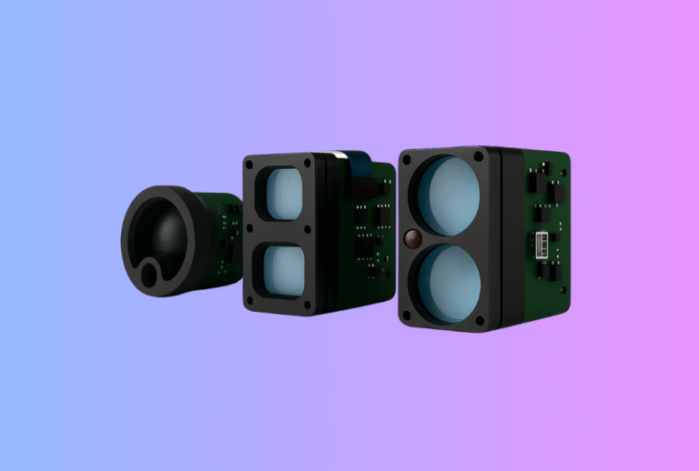
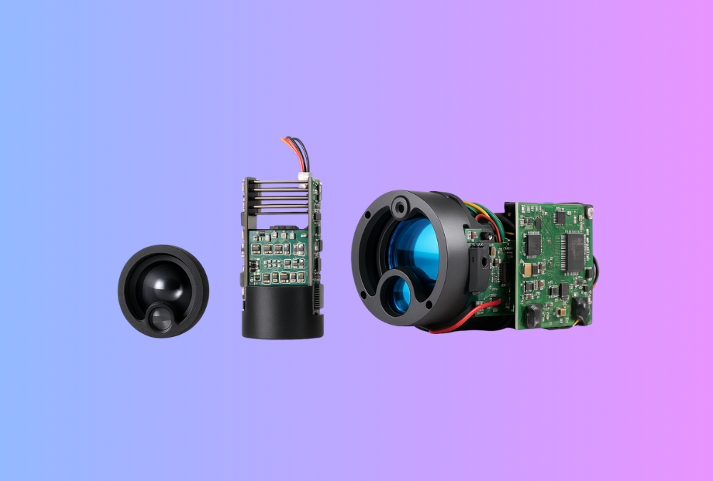
Start with our Laser Rangefinder Module options; we provide ROS 2/MAVLink reference drivers and PPS cabling notes.
Use Cases & Buyer Scenarios
UAV mapping with time-aligned LRF
GNSS-disciplined autopilot → MAVLink → companion computer → ROS 2. Your LRF’s hardware timestamp and the vehicle’s EKF timeline must agree, or geotags wander. Fuse with a Thermal camera module to validate targets at dawn/dusk and in foliage.
Thermal optics for hunting/outdoor brands
For Thermal Rifle Scopes, Thermal Monoculars, and Thermal Binoculars, deterministic timestamps keep range overlays stable during rapid panning and recoil—no “jumping” reticles when recording to NVRs or mobile apps.
Industrial/security integrations
In AMR/AGV, gates, and perimeter towers, latency budgets matter. Time-synced LRFs cut false alarms and make cross-camera correlation feasible. Add compact LRFs to Thermal Clip-On Sight-style stacks for portable patrol kits.
Spec & Selection Guide (the heart)
Parameters that decide if your time sync will actually work
-
Timestamp source: Prefer on-module hardware timestamps tied to PPS/PHC/PTP over host-arrival times. Map to ROS 2
Header.stamp. -
Clock domain: Choose one: OS system clock; ROS 2
/clock(simulation/log replay); PTP (IEEE 1588) for wired LANs; GNSS PPS + MAVLink TIMESYNC for UAVs or field rigs. -
Offset & jitter budget: Define max absolute offset (e.g., ≤1 ms UAV; ≤100 µs lab/PTP) and jitter (RMS) at the ROS topic.
-
Bridge policy: MAVLink
TIMESYNCcadence, monotonicity checks, and fallback toSYSTEM_TIMEwhen GNSS is missing. -
QoS: Use
SensorDataQoSfor LRF topics; ensure synchronizers (message_filters) and camera/IMU QoS are compatible. -
Replay & sim: When playing bags or simulating, set
use_sim_timeearly so all nodes consume/clock.
Time Sync Methods—what to use when
| Method | Typical accuracy | Where it shines | LRF integration notes |
|---|---|---|---|
| NTP (Chrony) | ~1–10 ms on LAN | Basic PCs, non-critical tests | OK for rough fusion; not for fast motion. |
| PTP (IEEE 1588 v2) | <1 µs on LAN with HW assist | Labs, fixed rigs, high-rate fusion | Requires NIC/switch support; excellent determinism. |
| GNSS PPS + serial/NMEA | 10–100 ns edge + message | Field robots, UAVs | LRF or carrier timestamps to PPS; bridge over MAVLink. |
| MAVLink | Sub-ms (depends link) | UAV autopilot ↔ companion | Built-in round-trip offset estimation and drift handling. |
Decision flow (simple but strict)
If single robot, wired LAN, and high-rate fusion → use PTP (IEEE 1588) with HW timestamp NICs.
Else if UAV/remote field rig → use GNSS PPS + MAVLink TIMESYNC and store offset/drift per session.
If sim or bag replay → publish /clock; set use_sim_time on all nodes before init.
Always stamp LRF with event time at the module/driver, never publish time from ROS.
Integration & Engineering Notes
Electrical & Interfaces (UART/USB/CAN/MAVLink/SDK)
-
PPS in, PPS out. Provide a 1 PPS input to discipline the LRF’s internal clock; expose a PPS pass-through when customers need to sync other sensors.
-
MAVLink bridge: Implement
TIMESYNCon the companion side and keep a running offset + skew estimate for the autopilot ↔ ROS bridge; apply it to convert LRF event times into the ROS clock. -
Time-stamped API: In SDKs, return
{range_m, snr, t_event_ns, n_returns}and a quality bitfield; never hide timestamp math inside smoothing filters. -
QoS & back-pressure: For ROS 2, publish LRF topics with
SensorDataQoSand set queue depths high enough to avoid drops when synchronizing with cameras/IMUs.
Optics & Mechanics (mounting, alignment, sealing)
-
Boresight still matters. Time sync won’t fix a mis-aligned LRF. Use V-groove/dowel datums so your boresight to thermal/EO is stable across builds.
-
Window torque consistency. Changes to gasket compression can alter divergence and SNR, which in turn affects confidence gating during sync tests.
-
Cable management. Keep PPS and UART/USB lines short and separated from motor drivers; bad EM layout shows up as timestamp jitter.
Firmware/ISP/Tuning (AGC, palettes, LRF fusion, ranging algorithm)
-
Hardware timestamps first. Timestamp at interrupt/service time for the return discriminator, then export raw ticks + conversion to ROS 2 time.
-
Drift control. If PPS is present, do a gentle slew (no step jumps) and log offset, drift ppm, and PPS lock state into the message or diagnostics.
-
MAVLink cadence. Keep
TIMESYNCexchange regular and reset on time jumps; fall back toSYSTEM_TIMEonly with a visible “degraded” flag. -
Fusion display. When overlaying on thermal video (e.g., Thermal Pistol Sights), interpolate range to camera shutter mid-exposure to avoid visual “swim.”
Testing & Validation (bench → field, acceptance criteria)
-
Bench harness: PTP grandmaster or GNSS PPS generator; measure (ROS topic stamp − ground-truth) for offset and RMS jitter vs load. PTP is the go-to for sub-µs LAN tests.
-
Message synchronizers: Validate with ROS 2
message_filters(Exact/Approximate) and make sure QoS settings allow pairing with cameras/IMUs. -
Acceptance gates: e.g., offset ≤1 ms (UAV) / ≤200 µs (lab); jitter ≤0.2 ms RMS; no monotonicity violations over 1 hr.
Compliance, Export & Certifications
-
Laser & EMC: Time sync doesn’t change your safety/EMC scope. Continue to certify IEC 60825-1 (Class 1/1M) and CE/FCC/UKCA for emissions/ immunity; time wiring (PPS/USB/CAN) must meet the same EMC plan.
-
Records: Keep time-sync calibration and GNSS/PTP configuration in your CoC pack; distributors often audit reproducibility.
Business Model, MOQ & Lead Time (OEM/ODM)
-
Reference kits: Include PPS pigtail, ROS 2 sample node (C++/Python), MAVLink bridge with
TIMESYNC, and a launch file with QoS presets for camera/IMU sync. -
Sampling: 2–4 weeks for standard PPS-ready SKUs; 4–6 weeks for custom connectors or autopilot-specific cables.
-
MOQ: 50–200 pcs for standard LRFs; 300+ when custom enclosures/ windows are required.
-
Distributor ROI example
| Driver | Baseline | With time-sync kit | Units/yr | Impact |
|---|---|---|---|---|
| Integration weeks (first customer) | 4 | 2 | — | ↓ services cost |
| Field bugs from timestamp mismatch | 8 | 3 | — | ↓ RMAs / truck-rolls |
| Attach rate (LRF + thermal) | 35% | 50% | 1,000 | ↑ revenue from bundles |
Pitfalls, Benchmarks & QA
Seven common mistakes
-
Stamping publish time, not event time. Breaks fusion immediately. Use
Header.stamp= capture time. -
Mixing clock domains. Some nodes use system time; others follow
/clock. Decide and document. -
Relying on NTP for aerial mapping. It’s millisecond-scale; use PPS +
TIMESYNCor PTP. -
Ignoring QoS mismatch.
ReliablevsBestEffortcauses synchronizers to starve. -
No monotonicity checks. Let bridges reset if a jump is detected; log and degrade gracefully.
-
Hidden filters. Drivers that smooth timestamps ruin diagnostics; always export raw event time and drift.
-
Un-tested replay/sim. If you don’t enable
/clockbefore node init, bags/sims won’t be consistent.
Benchmark recipe (repeatable)
-
Static course: Place a matte target at fixed distances; log LRF range with ground-truth and PPS/PTP.
-
Dynamic sweep: Pan/tilt while logging camera + LRF; verify that range aligns to shutter mid-points.
-
Stress: CPU load, network congestion, and object distance changes; assert offset/jitter thresholds.
FAQs
1) Is PTP really better than NTP?
On a LAN, PTP (IEEE 1588) can reach sub-µs accuracy with the right NIC/switch hardware; NTP is usually ms-level—fine for desktops, not for fast fusion.
2) Do I need GNSS PPS if I already use PTP?
In the lab, PTP is great. In the field or in UAVs without stable Ethernet, GNSS PPS + MAVLink TIMESYNC is the pragmatic option.
3) How do ROS 2 clocks and /clock work?
ROS 2 supports system time and ROS time (from /clock). When use_sim_time is set, nodes read /clock—critical for simulation and log-replay consistency.
4) What should the LRF driver publish?
A stamped message with event time, range, confidence/SNR, return count, and diagnostics (offset, drift, PPS lock).
5) What about MAVLink SYSTEM_TIME?
Use it as a coarse reference; rely on TIMESYNC for round-trip offset estimation and drift compensation.
6) Can message_filters fix bad clocks?
No; they only match messages. Fix clock alignment first, then choose Exact or Approximate policies with compatible QoS.
7) Does this change laser safety or EMC?
No—but adding PPS and high-speed links means you should revisit EMC layouts. Laser safety (IEC 60825-1) remains unchanged.
Call-to-Action (CTA)
Building a UAV payload or multi-sensor robot? We’ll deliver an LRF + ROS 2 + MAVLink reference stack with PPS, TIMESYNC, and boresight docs—plus a bench plan to prove offset/jitter. Start with our Laser Rangefinder Module and tell us your autopilot, networks, and accuracy targets.