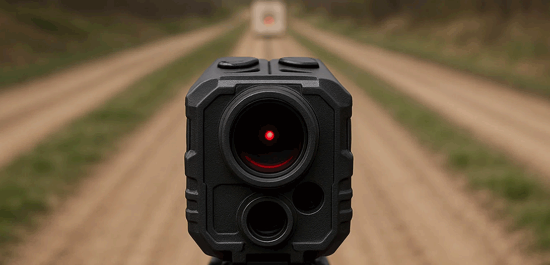
When a hunter presses the range button, the number that appears must be fast, steady, and believable. That confidence is engineered into the laser rangefinder module first, then preserved by the way you align optics, tune firmware, and harden the housing against recoil and weather. This article is a field-realistic guide for outdoor-optics brands integrating LRF cores into hunting binoculars and scopes, with a focus on practical geometry, human factors, and an integration rhythm you can ship.
Table of Contents
ToggleWhy a module-first approach wins for hunting glass
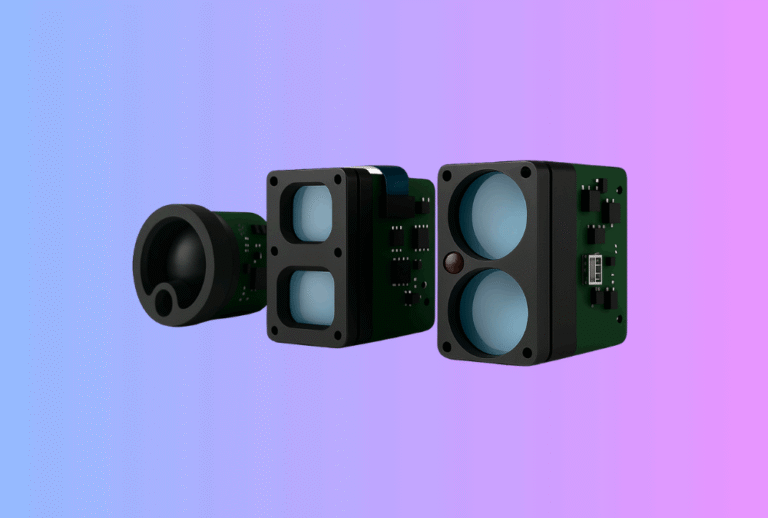
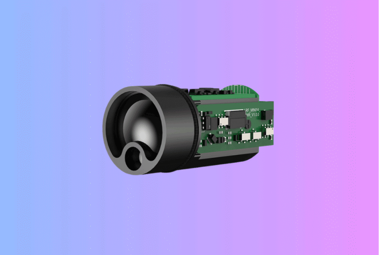
Hunting optics live in a world of recoil, cold starts, dust, rain, and gloved hands. A module-first approach lets you standardize the ranging “engine” and scale it across form factors without re-learning physics every time. The right laser rangefinder module should expose clean serial control, return multiple echoes with a confidence score, and come with a clear Class 1 eye-safety dossier so your legal text and labels stay consistent across regions. That foundation helps you build a family—binoculars for glassing, scopes for immediate holds, and mixed daytime–nighttime kits—without reinventing the ranging logic per SKU.
Technical core (docs, commands, and integration support): Laser Rangefinder Module
What “good ranging” means in binoculars vs. scopes
Binoculars are glassing tools first. Users scan while breathing, often at 8–10× magnification, stabilizing with two hands. The rangefinder must feel “calm” while panning, so the spot should be tight enough horizontally to avoid painting trunks, but slightly forgiving vertically to tolerate micro-tremor and terrain shifts. The HUD needs thin, readable reticles that do not mask small animals or partial targets in brush.
Scopes invert the priority: the sight picture and shot cadence matter first; the range feeds a solver, subtensions, or a quick mental hold. The platform is steadier—supported kneel, bipod, bag—so you can afford a tighter beam/FOV pair that isolates the target at 300–800 m. The design challenge shifts to boresight retention under recoil, ensuring the LRF path and optical axis stay married after temperature cycles and range sessions.
Across both, the most common failure has one root cause: mismatch between beam footprint and receiver field of view. If the receiver FOV is far wider than the laser spot, bright backstops dominate returns; if it is too tight, users “fall off” the sensing cone while panning. The cure is geometric: choose FOV to just envelope the spot at your working ranges—something you can only do after you measure divergence consistently on the bench.
Beam divergence that works in the field
Beam divergence is the far-field angular spread; the spot diameter grows roughly linearly with distance for a given definition. In real products, the beam is often elliptical due to emitter and collimator geometry. Treat the axes differently:
-
- Hunting binoculars: a balanced starting point is ~2.2 × 1.2 mrad (H×V, full-angle). Horizontally, you reduce overlap with trunks and rocks; vertically, you gain scan forgiveness for a standing user.
-
- Day scopes: ~1.8 × 1.0 mrad is a sensible launch point when the platform is steadier and ranging typically extends past 300 m.
-
- Thermal clip-on stacks: a slightly taller vertical axis—for example ~2.5 × 1.5 mrad—can feel calmer when the shooter is parsing a thermal image and a distance simultaneously.
These are starting points, not standards. Your glass diameter, coatings, detector noise, and firmware will move the final numbers. The non-negotiable rules are: (1) keep a single definition throughout your docs (full-angle, 1/e² unless otherwise stated), and (2) size receiver FOV to match the spot at your intended ranges.
Wavelength, SNR, and the 905-vs-1550 question (practical, not doctrinal)
You’ll hear blanket claims that 1550 nm “wins” because it’s “safer” and thus enables “more power.” Reality is system-level. Eye-safety classification (Class 1) is about accessible emission under the test standard, not a magic wavelength. Practical SNR depends on detector choice, optics efficiency, and ambient background. With careful optics and signal chain, a 905 nm build can rival 1550 nm at consumer power budgets and form factors—especially at dawn/dusk when solar NIR background is low. Pick a wavelength for your total system trade-offs (supply chain, optics, detector, cost), and build safety from the classification math, not from folklore.
DSP that chooses the right echo in brush
Vegetation scenes create multiple returns: a first echo off a leaf, a second off a branch, and a later one off the target itself. Good firmware rarely trusts “first” or “strongest” by default. Instead, it:
-
Captures multiple returns per shot and clusters by range gate so a scatter of faint leaf hits doesn’t masquerade as your target.
-
Applies a closer-target bias appropriate for hunting (your animal or marker is usually in front of bright backstops).
-
Requires short temporal confirmation (N-of-M frames) before declaring a “lock” or firing haptics.
-
Surfaces a confidence metric with the range so the HUD or haptic only celebrates when the evidence is actually strong.
This behavior feels human: the number appears quickly, then “decides” with a tiny pause that tells the shooter “you can trust it.”
Recoil, boresight, and mechanical discipline
A well-designed range stack starts with mechanics, not code. Even with a coaxial emitter/receiver, boresight drift after a recoil cycle can move the spot by several milliradians at 300 m—devastating in timber. Solve it early:
-
Keyed interfaces for the emitter barrel and receiver block prevent micro-slip.
-
Controlled torque and adhesives in a written SOP stop slow creep.
-
Alignment re-checks after thermal cycling and recoil prove that the collimation you measured on the bench survives the field.
The ruggedization habits you may already use in your night portfolio translate directly. For examples of recoil-ready interfaces and sealing discipline, see Thermal Rifle Scopes and Thermal Clip-On Sight.
HUDs that help at dawn
Low light is kind to detectors (less solar background) but unforgiving to eyes. Keep the HUD readable and quiet:
-
Auto-dimming that follows a logarithmic-like curve preserves contrast without blooming.
-
Thin reticles reveal small targets in brush; heavy icons hide more than they help.
-
Latency budgeting matters: if the range settles in < ~100 ms, the brain perceives it as instant; slower loops teach users to chase numbers.
We apply similar pipeline discipline—latency budgets, AGC control, sunlight readability—in imaging products. If you plan daylight products that ladder into night, the UX and display lessons carry into your observation line: Thermal camera module, Thermal Binoculars, and Thermal Monoculars.
A concise, honest comparison (illustrative targets)
Use this as a starting map for optics, electronics, and firmware teams. Tune for your glass, coatings, and detectors.
| Parameter | Hunting binocular (general) | Day scope + LRF | Thermal/clip-on stack |
|---|---|---|---|
| Emitter / Safety | 905 nm / Class 1 | 905 or 1550 nm / Class 1 | 905 nm / Class 1 |
| Beam divergence (full-angle) | ~2.2 × 1.2 mrad | ~1.8 × 1.0 mrad | ~2.5 × 1.5 mrad |
| Receiver FOV (approx.) | ≤ 3 mrad | ≤ 2 mrad | ≤ 3–4 mrad |
| Scan feel | 8–12 Hz, steady | 10–12 Hz, solver-feed | 8–10 Hz, brush-aware |
| Alignment priority | Hand stability | Boresight & recoil | Boresight w/ add-on |
| Range window (typical) | 50–700 m | 100–800 m | 50–600 m |
The point of the table isn’t the exact numbers—it’s the discipline of picking geometry first, then matching FOV and firmware so the field experience aligns with what your sheet promises.
Validation the field will respect
Bench: Build a two-distance NIR imaging rig (e.g., 25 m & 75 m) with ND filters. Fit Gaussian profiles in X/Y and record 1/e² widths. Convert everything to full-angle before comparison. Store the plots and numbers with your incoming QC files so every change of emitter, lens, or coating triggers a re-verification.
Field: Test open country, timber/brush, and rocky backdrops. At each site, run multiple scans at 100/200/300/500 m on natural targets and reflectors. Log lock rate, mean lock time, false-lock %, and the confidence distribution. In brush, annotate the scene by occlusion ratio (rough estimate of how much of the target the vegetation covers inside the reticle). Publish a one-page “brush card” with photos and numbers—retailers love it, and engineers can reproduce it.
After-stress: Thermal cycle (−10 °C → +50 °C) and a recoil sequence matched to the platform. Re-verify boresight, divergence, and AEL margin. Drift often hides until the last mile; catching it here prevents field returns.
Electrical and interface notes that actually shorten schedules
A hunting-ready laser rangefinder module should speak UART for mode control and return streaming, reserve USB for firmware updates and log pulls, and provide a concise SDK with: range(s), return strength, confidence, timestamp, and a stable flag. If you’re feeding a ballistic solver, the solver should accept ranges only when “stable” is true and confidence exceeds a threshold—otherwise the reticle and math fight the user.
Power behavior matters: cold-start current spikes, brown-out thresholds, and display inrush can create “mystery reboots” in winter. Budget and test for them early. For Bluetooth or app ecosystems, sync profiles by rifle (zero, velocity, drag model), not by user, to prevent camp-night mix-ups.
Firmware that feels like a calm spotter
Design the ranging loop as a conversation between motion and evidence:
-
Acquire: short range-gate sweep; take the first plausible return but don’t publish yet.
-
Evaluate: is there a closer cluster within the gate? Are returns consistent across N/M frames?
-
Confirm: publish range + confidence; trigger haptics only if confidence ≥ threshold and the closest cluster persists.
-
Hold & decay: freeze the number briefly, then decay confidence if motion resumes or evidence weakens—this avoids “number flicker.”
Users will describe this as “the number appears fast and then settles,” which is exactly the perception you want in binoculars and scopes.
UI and documentation that reduce returns
Most customer returns are not electronics—they’re expectations. Two artifacts pay for themselves:
-
A one-page quick-start that shows the reticle, the confidence icon, and what “stable” looks like before the haptic buzz.
-
A safety page that uses the same photos and labels as your shipped device. Class 1 eye-safety language belongs here, alongside the exact location of labels on the product. Consistency between paper and device earns trust at retail counters.
If you sell daylight kits that ladder into night, make the step-up path obvious: “baseline day ranging” plus optional observation at dusk with Thermal Monoculars or Thermal Binoculars; advanced shooters can move into Thermal Rifle Scopes or compact carry platforms like Thermal Pistol Sights. Keep the daytime UX constant so skills transfer cleanly.
Putting it together: a reference architecture you can ship
-
Optics: AR-coated window; emitter collimated for ~2.2 × 1.2 mrad (binoculars) or ~1.8 × 1.0 mrad (scopes); receiver FOV matched to spot at 200–300 m; internal baffling for stray-light control.
-
Electronics: Low-noise detector front-end; temperature-aware gain; brown-out immunity; clean haptic driver.
-
Firmware: Multi-return capture, closest-cluster selection, N-of-M confirmation, ambient-aware thresholds; confidence-gated haptics.
-
Mechanics: Keyed mounts; torque/adhesive SOP; drop and recoil-tested; alignment re-check after stress.
-
Quality file: Two-distance divergence report (plots + numbers), Class 1 AEL calculation, label artwork, and user-manual safety pages.
This architecture can anchor a binocular today and a scope tomorrow, while also coexisting with a nighttime observation line built around our Thermal camera module.
FAQs (focused on hunting binoculars & scopes)
Do I need 1550 nm to be eye-safe?
No. Class 1 is achievable at 905 nm with appropriate optics and emission budgeting. Choose wavelength based on total system trade-offs, then prove safety in your classification file.
Why does low light sometimes feel easier and sometimes harder?
Dusk lowers solar background (good for SNR) but often adds mist or dew (more backscatter) and deep shadows in brush (more partial occlusions). Your thresholds and clustering must adapt.
What latency feels “instant” in a scope HUD?
If the range stabilizes in < ~100 ms, most shooters perceive it as immediate. Slower loops teach them to chase numbers.
How do I measure divergence without a profiler?
Use two-distance NIR imaging with ND filters. Fit Gaussians and report full-angle 1/e²; if you use FWHM, convert and state it clearly so suppliers and teams compare apples to apples.
Can the same core serve binoculars and scopes?
Yes—if you control alignment and present ranges with confidence gating. Many brands ship one LRF core across binoculars, day scopes, and mixed day/night platforms, changing only optics and UI shells.
Call-to-Action
If your next binocular or scope line must range quickly, survive recoil, and ship Class 1 cleanly, start with a core that respects optics, firmware, and compliance equally. Our engineering team can help you pick divergence/FOV, implement multi-return clustering, and assemble an IEC-aligned safety file—then private-label the finished devices for your channels.
Start here: Laser Rangefinder Module
Night & observation step-ups: Thermal Binoculars · Thermal Monoculars · Thermal Rifle Scopes · Thermal Clip-On Sight · Thermal Pistol Sights · Thermal camera module
Sources
-
FDA — Laser Products: Conformance with IEC 60825-1 Ed. 3 (Laser Notice No. 56); guidance and PDF, 2023. U.S. Food and Drug Administration+1
-
FDA — Notices to the Laser Industry (LN56 context and related guidance), 2024. U.S. Food and Drug Administration
-
RP-Photonics — Beam Divergence (definitions; half/full-angle; 1/e²), Gaussian Beams (background). RP Photonics+1
-
Gentec-EO — Quick guide on beam divergence measurement; Beam divergence & diameter calculator. Gentec-Eo+1
-
Laser Focus World — Safety questions raised about 1550 nm lidar (nuanced wavelength/safety discussion).
-
Buchner et al., 2021 — Analytical Evaluation of SNR for APDs and SPADs (open-access). PMC
-
onsemi, 2023 — Analytical Evaluation of SNR for SiPM & APD at 905/1550 nm (app note). onsemi