Lead:
Pulsed rangefinders live and die by timing. Set pulse repetition frequency (PRF) correctly and discipline clocks to GNSS/IMU, and a handheld or UAV sees the distance you meant—fast, stable, and legally clean. This article explains, in practical terms, how to choose PRF and build a time base that keeps a laser rangefinder module honest in outdoor optics and UAV work.
Table of Contents
ToggleExecutive Summary
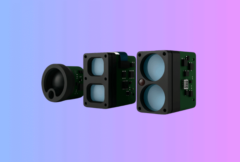
A module-first program succeeds when timing feels invisible to the user. PRF governs unambiguous range, average emission under IEC 60825-1 Class 1, and how “snappy” the HUD or flight stack feels. Synchronization turns single ranges into truth other subsystems can act on: GNSS 1PPS anchors absolute time, a monotonic counter gives microsecond resolution, and the IMU contributes pose at the same epoch so logs and controllers don’t argue. If you treat these as architecture—not afterthoughts—you can reuse one core across hunting binoculars, scopes, and UAV mapping payloads with only optics and UI changed. For command sets, reference behaviors, and serial examples, start at Laser Rangefinder Module.
Why PRF is the metronome of ranging
A pulsed rangefinder measures time of flight between a transmit pulse and the received echo. The space between pulses is the pulse repetition interval; its inverse is PRF. Three realities flow from that simple knob.
First, PRF sets unambiguous range. If you do not explicitly label each shot and associate returns, any echo that arrives after the next shot can be misinterpreted as belonging to that later pulse. The boundary is Ru=c/(2⋅PRF)R_u = c/(2\cdot PRF)Ru=c/(2⋅PRF). Set PRF too high for your mission and you will occasionally “wrap” long echoes into the wrong epoch. On a façade approach this shows up as a jumpy number at 35–45 m; in timber it looks like a rare, impossible reading you can’t reproduce on the bench.
Second, PRF sets average emission and therefore interacts with eye-safety limits and thermal budgets. Average optical power scales with PRF times pulse energy. If you raise PRF to make the UI feel lively, you may have to trim energy per shot to stay inside Class 1, which trims signal-to-noise at long range or on dark targets. The AEL math in IEC 60825-1 forces these trade-offs; design teams that acknowledge them early ship on time.
Third, PRF makes a human-factors promise. Shooters and pilots perceive sub-100 ms updates as “instant.” That can be achieved with a moderate PRF and a short confirmation window (for example an N-of-M policy over 120–250 ms) rather than with a raw firehose of pulses. The fastest system is not the one with the highest PRF; it is the one whose timing and decision logic align.
Use cases where timing quality shows up in the field
UAV mapping and façade standoff
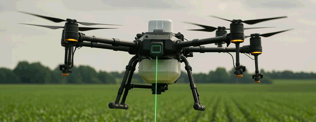
A down-looking rangefinder stabilizes AGL near terrain, and a forward-looking unit keeps a multirotor honest as it creeps from 40 m to 5 m. Here PRF must be high enough to maintain a 10–20 Hz publish rate with modern controllers while preserving RuR_uRu comfortably beyond the working distances. Deterministic time-tags matter: camera triggers, ranges, and IMU samples have to agree about “now.” The simplest route is a GNSS 1PPS into the payload and a common epoch distributed to the flight computer and companion processor via the autopilot’s PPS pin or PTP. If you later add night capability, fusing distance with a thermal centroid is straightforward when every message carries epoch and age-since-sample. (For fused perception, see Thermal camera module.)
Hunting binoculars and scopes
A hunter expects “press → honest number.” In brush, multiple echoes arrive; in cold, batteries sag and clocks wander. A moderate PRF with explicit shot IDs gives firmware the time to cluster echoes and gate a haptic only when the nearest stable cluster persists for a few frames. If you log to a phone app, tag ranges to GPS time; field returns go faster when the evidence is anchored to a universal clock. These discipline habits are the same ones we use in Thermal Rifle Scopes and Thermal Clip-On Sight—latency budgets, stable boresight, visible “confidence.”
The selection guide (the heart): choosing PRF and a time base
The safest way to pick PRF is to begin with the geometry and surfaces you will face, then work backwards from RuR_uRu, average power, and the user’s sense of responsiveness.
1) Define the job in one sentence. “Down-look altimeter at 3–20 m AGL over brush,” or “forward-look standoff 5–60 m on concrete, steel, and glass.” If your sentence includes distances longer than RuR_uRu at your tentative PRF, either lower PRF or plan to tag pulses (each shot gets a small ID) and carry a return buffer. Pulse tagging lets you push PRF higher without ambiguity, but it requires careful firmware, a ring buffer, and good tests.
2) Budget average emission first. You will not negotiate with Class 1 limits after tooling. For a given emitter and aperture, decide how much average power the system can dissipate and what AEL gives you. That budget determines the rectangle of “(pulse energy, PRF)” available. If you must ship with the UI faster than that rectangle allows, it is time to adjust optics efficiency, not fudge the math.
3) Translate responsiveness into a confirmation window, not just PRF. Most fielded products feel decisive when the first plausible range appears quickly and the device “decides” a hundred milliseconds later. That is a confirmation window choice—N-of-M frames—tied to your PRF. A system at 10 Hz with a 5-frame window feels calmer than a 30 Hz system that publishes every estimate immediately.
4) Decide how the clock will be told what time it is. The module needs a monotonic microsecond counter for shot scheduling and time-stamps, disciplined to 1PPS from a GNSS receiver. “Disciplined” means slowly slewed, not stepped; hard steps clump shots and upset controllers. On a UAV, carry that epoch to the autopilot and companion via PPS and, where appropriate, PTP on the onboard network. On a handheld, you can log absolute time with GPS or phone-supplied UTC and keep the module’s internal clock monotonic between syncs.
5) Align the receiver’s field of view with the beam. Timing can’t rescue poor geometry. If FOV dwarfs the beam footprint at your working ranges, the receiver integrates backgrounds and makes PRF look random. Size FOV to just envelop the spot for the distances you care about; then pick PRF.
A small table helps anchor the conversation:
| Mission | Sensible PRF | Minimum unambiguous range RuR_uRu | Publish cadence | Notes |
|---|---|---|---|---|
| Down-look altimeter (3–20 m AGL) | 5–20 Hz | ≥ 50 m | 10–20 Hz | Confirmation favors floor/ground echoes |
| Façade standoff (5–60 m) | 10–30 Hz | ≥ 120 m | 10–20 Hz | Narrow FOV; closest-cluster bias |
| Binocular/Scope ranging | 8–12 Hz | ≥ 600 m | 8–12 Hz (UI) | Haptic on high confidence only |
These numbers are typical starting points, not promises; optics efficiency, target reflectance, and firmware will shift the final choices. But the pattern holds across programs: pick PRF so RuR_uRu covers the job or adopt per-pulse IDs; define a confirmation window; and carry epoch and age with every range.
Building the time base without drama
Time sync works when each layer does the smallest thing that can possibly work and no more.
Inside the module, the microcontroller runs a monotonic microsecond counter and schedules shots off that base. A GNSS 1PPS edge arrives once per second and is measured against the counter. Rather than yanking the counter to the PPS edge, the firmware slews the local tick rate so the counter converges over a few seconds. That keeps pulse spacing regular. At the instant each shot is fired, the module notes the counter value and assigns a shot ID if you’re operating beyond RuR_uRu. When an echo crosses threshold, the module records the time-stamp, associates it with the shot ID, and computes age (now minus echo time).
On a UAV, pass PPS into the autopilot or companion and treat that line as the shared epoch. The module publishes ranges with epoch + age; the flight stack consumes them as DISTANCE_SENSOR or RANGEFINDER messages and discards samples whose age exceeds a policy (for example > 100 ms). If you stream through a companion computer, establish a PTP domain on the onboard network so your logger, camera trigger, rangefinder process, and autopilot share the same seconds.
With an IMU, there are two easy patterns. The first is to latch the IMU’s data-ready interrupt at the module and record that time in the same microsecond base; de-skew is then a simple subtraction. The second is to let the IMU publish its own time in PPS-disciplined units and align in the companion. Either is fine; what breaks systems is mixing monotonic counters with wall-clock time and assuming they are the same.
Algorithms that make PRF feel calm
Brush, cables, trusses, and chain-link produce multiple echoes. In a scope, the right answer is almost always the closest consistent cluster; in down-look altimetry, it is the floor. A well-behaved loop does three quiet things. It captures more than one return per shot. It clusters returns inside a narrow gate that reflects real physics rather than marketing folklore. And it defers celebratory signals (haptic, tone, solver ingest) until the nearest cluster persists for a moment. PRF only determines how many opportunities you have to evaluate evidence; judgment is the firmware’s job.
The second quiet behavior is ambient-aware thresholds. At dusk, solar NIR falls and the receiver sees deeper into vegetation; weak glints become visible. If thresholds do not adapt, you will suddenly “discover” returns the system should ignore and your false-positive rate will rise while users swear the device is haunted. Tie thresholds to an ambient proxy or to observed noise statistics rather than to a fixed number.
The final habit is to publish confidence with every range. Whether you encode it 0–100 or as a covariance, the downstream consumer—human or controller—must know when to trust the number. Pilots understand a range ribbon that fades with low confidence; shooters understand that the buzz is a promise, not a suggestion.
Mechanical and optical discipline that timing cannot fix
A perfect clock does not rescue a drifting boresight. If your emitter barrel or receiver block can creep under vibration or temperature, the spot you so carefully measured on the bench will march off-axis in the field. Key interfaces. Control torque and adhesives. Re-verify alignment after thermal cycles and recoil or vibration dwell. Recess and AR-coat windows; stray-light control at noon stabilizes daytime behavior more than late firmware tweaks. These are the same habits we use in Thermal Binoculars and Thermal Monoculars, where sunlight readability and sealing are non-negotiable.
Validation: how to prove timing and PRF choices
A good test plan fits on one page yet survives an audit.
On the bench, feed a disciplined PPS and log the module’s shot schedule and time-stamps for fifteen minutes. You are hunting two numbers: shot-to-PPS jitter and long-term drift. If you see hard steps, the discipline loop is stepping, not slewing. In parallel, measure divergence at two distances with an NIR-sensitive camera and neutral-density filters, fit Gaussians in X and Y, and record full-angle 1/e² widths and axis ratio. Archive the plots with the firmware hash; they are part of the quality file and the Class 1 dossier.
In flight, fly a façade approach from 40 m to 5 m at two speeds and log range error versus tape or total station along with age and confidence. Then run a terrain-follow sequence over scrub and a short auto-land to see how the down-look policy handles vegetation and flare. At low light, repeat both tests from golden hour into civil twilight to verify that ambient-aware thresholds hold the false-positive rate steady. Conclude with a post-stress check after a thermal cycle and vibration dwell; re-verify boresight, timing jitter, and window integrity.
If you publish that one-pager with your OEM bundle, procurement and pilots will both trust you sooner.
Compliance and operations context
Timing discipline does not replace legal discipline. The path that travels well across regions is to design and document to IEC 60825-1 (Ed. 3) Class 1 and follow the U.S. policy in Laser Notice No. 56, which recognizes IEC conformance and explains labels and record-keeping. Keep the AEL worksheet, label artwork, and test setups in the same revision system as your optics drawings so a change of emitter, coating, or PRF triggers re-verification without argument. For UAV programs, remember that Part 107 operating rules—including night and operations over people—apply regardless of payload; ensure your wiring and mounts do not shadow Remote ID antennas and that your integration plays well with flight-controller timing.
Business model that respects engineering
Sampling that includes the PPS harness, UART/USB access, and timing scripts is far more helpful than a bare sensor. Pilot kits in two to four weeks, followed by first-article approval and SOP inside a quarter, are realistic when labels and test jigs are fixed early. The most convincing sales artifact is not a long datasheet; it is the flight card—standoff error, latency distribution, and false-lock rate under three scenarios. One core—documented PRF, PPS pins exposed, and a compact SDK—can then carry a family of products without arguments between firmware and marketing.
FAQs
Do I need to lower PRF whenever I extend range?
Only if you operate without shot IDs. If each pulse is identifiable and your buffer is sized, you can run higher PRF than RuR_uRu suggests while preserving unambiguous association. Most consumer builds still pick PRF such that RuR_uRu exceeds credible distances to keep firmware simple.
Why not discipline the clock by stepping to PPS?
Hard steps clump pulses and perturb controllers. Slew the tick rate so the local counter glides to the PPS edge over a few seconds; the shot pattern will stay regular.
What latency feels immediate to humans and controllers?
If the number “settles” within about 100 ms, shooters and pilots perceive it as instant. That behavior is a combination of PRF and decision window, not PRF alone.
Is 1550 nm required for safety or timing accuracy?
No. Safety follows Class 1 AEL math and labeling, not wavelength myths; timing accuracy follows clock discipline and architecture. A well-built 905 nm system can meet Class 1 and perform excellently with the right optics and sync.
How do I time-align IMU and range for post-processing?
Either latch the IMU IRQ with the module’s PPS-disciplined counter and record the timestamp, or run both sensors in a PTP domain and compare epochs directly. In all cases, carry age with each measurement so stale data never drives a controller.
Call-to-Action
If your next outdoor-optics or UAV program needs timing that never lies—PRF chosen for the mission, GNSS/IMU sync that holds across temperatures, and a Class 1 safety file that matches the device—we can help. Our core exposes PPS pins, UART/USB, and examples for MAVLink and PTP so you move from bench to field without detours.
Start here: Laser Rangefinder Module
Fuse with imaging when needed: Thermal camera module · Thermal Binoculars · Thermal Monoculars
Sources
-
FDA — Laser Products: Conformance with IEC 60825-1 (Laser Notice No. 56), Feb 2023. FDA
-
IEC — IEC 60825-1:2014 Safety of laser products – Part 1 overview (webstore page). IEC Webstore
-
IEEE — IEEE 1588-2019 Precision Time Protocol (PTP) — standard overview. IEEE Standards
-
MAVLink — Common message set & developer docs (PX4/ArduPilot ecosystem). mavlink.io
-
NREL — Reference Solar Spectra (AM1.5 / ASTM G-173) — background NIR context. NREL