In warehouses, factories and logistics centers, mobile robots and AMRs are no longer pilot projects—they are core infrastructure. As fleets grow from a few units to hundreds, operators discover that standard 2D LiDAR and RGB cameras are not enough. They struggle with dark aisles, reflective floors, steam, dust and people wearing dark clothes.
Table of Contents
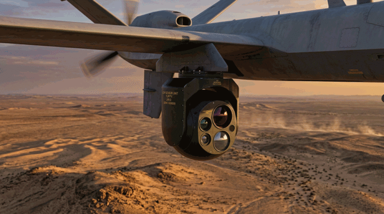
ToggleThat is where thermal imaging modules enter the picture. By sensing heat instead of visible light, they give robots a stable view of people, forklifts, pallets and hot equipment 24/7, independent of ambient illumination. But dropping a thermal module onto a robot is not just “adding another camera.” You must rethink field-of-view planning, end-to-end latency and functional safety.
This article is written from the point of view of a China-based manufacturer of OEM thermal camera modules working with mobile robot integrators worldwide. It focuses on engineering decisions, not marketing: what actually matters when you integrate a thermal module into your AMR perception stack.
1. Why mobile robots and AMRs need thermal imaging
Most mobile platforms today use a familiar sensor set: 2D LiDAR for navigation and obstacle detection, ultrasonic sensors for close-range safety, plus one or more RGB cameras for barcode reading, localisation or tele-operation. In many environments this works—until it doesn’t.
Typical pain points include:
- Poor lighting and high contrast. Dark aisles, back-lit dock doors and night shifts make RGB detection unreliable.
- Visual camouflage. Workers in dark clothing, black pallets or shrink-wrapped loads blend into the background.
- Environmental disturbances. Steam, dust, smoke and headlights from forklifts confuse visible cameras and even LiDAR in extreme cases.
- Thermal risk sources. Batteries, chargers, motors and conveyor bearings can overheat without visible change.
Thermal imaging modules address these issues by providing:
- Consistent detection of people and vehicles based on body heat and motor temperature, not color or texture.
- Visibility in complete darkness—no extra lighting or IR illuminators required.
- Early warning of hot spots on chargers, racks or equipment that might start a fire or lead to unplanned downtime.
For OEMs and system integrators, the question is no longer whether to use thermal imaging, but how to integrate it in a way that meets safety, performance and cost targets.
2. Where the thermal imaging module fits in the robot perception stack
A robot or AMR is more than a collection of sensors; it is a tightly coordinated system. To use a thermal module effectively, you must understand its role among LiDAR, ultrasonics and RGB/3D cameras.
2.1 Core elements of a robot-grade thermal module
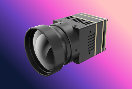
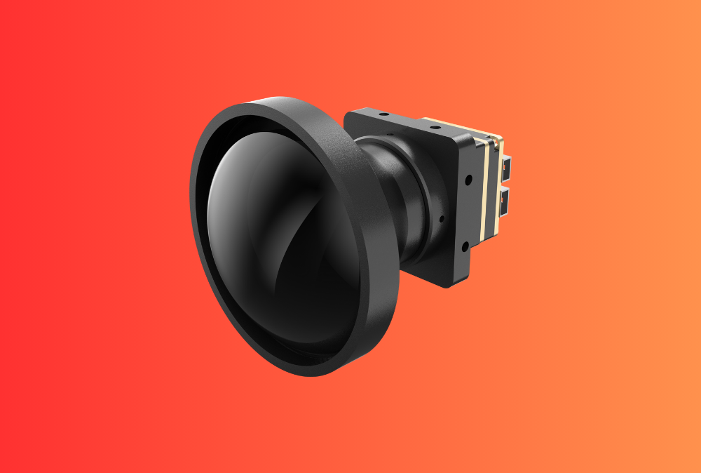
From a hardware standpoint, an AMR-ready thermal module usually includes:
- an uncooled LWIR microbolometer (for example 256×192, 384×288 or 640×512 pixels);
- a ruggedised lens assembly matched to the pixel pitch and FOV;
- integrated shutter or shutter-less NUC algorithms to control drift;
- a processing board that outputs digital video (e.g., Y16, RAW, or encoded) and optional temperature data;
- electrical and mechanical interfaces designed for OEM integration.
Gemin’s OEM thermal imaging modules follow this pattern: a compact core that handles sensor driving, AGC and basic image enhancement, while giving the robot developer access to radiometric data and configuration parameters.
2.2 Multi-sensor fusion, not replacement
Thermal is rarely a complete replacement for LiDAR or RGB. Instead, it becomes another layer in the perception stack. Common architectures include:
- LiDAR handles geometric navigation and obstacle detection;
- thermal imaging provides human / vehicle detection and hot-spot monitoring;
- RGB or 3D cameras handle fine-grained classification, barcodes and localisation markers.
The robot’s safety controller or central compute then fuses these streams: for example, a person detected in thermal can confirm or override a noisy LiDAR return in a dusty aisle.
2.3 Interfaces and synchronisation
For mobile robots, interfaces must be both robust and easy to integrate:
- Ethernet or GMSL for longer cable runs and noisy industrial environments;
- MIPI or parallel interfaces for short-range, high-bandwidth connections to embedded SoCs;
- precise timestamps and support for PTP or similar synchronisation, so detections can be aligned with LiDAR and wheel odometry.
An OEM-focused module should expose clean APIs or SDKs for configuration (gain modes, palettes, temperature ranges, ROI settings) and deliver both video and meta-data to the robot’s perception software.
3. Field-of-view planning for mobile robots and AMRs
Most first-time integrators underestimate how important field-of-view (FOV) planning is. Using a “nice wide lens” sounds attractive, but the wrong FOV can either miss critical areas or flood your AI pipeline with unnecessary data.
3.1 Horizontal and vertical FOV vs coverage
For a given FOV and mounting position, you can calculate how much ground the camera sees at different distances. A simple rule of thumb is:
coverage width ≈ 2 × distance × tan(FOV/2)
For example, with the camera mounted at the robot’s height:
| Horizontal FOV | Coverage width at 5 m | Coverage width at 10 m |
|---|---|---|
| 24° (narrow) | ≈ 2.1 m | ≈ 4.2 m |
| 50° (medium) | ≈ 4.7 m | ≈ 9.3 m |
| 90° (wide) | ≈ 10 m | ≈ 20 m |
Narrow FOVs give more pixels on target at longer ranges, which is useful for aisle-end monitoring and high-speed robots. Wider FOVs cover more area near the robot but reduce angular resolution, making long-range classification harder.
In practice, many AMR integrators choose:
- around 50° H-FOV for forward-looking obstacle detection;
- 70–90° for short-range safety monitoring or side coverage;
- or a combination of one medium FOV front camera and wide FOV secondary cameras.
3.2 Mounting height and tilt angle
Mounting position affects what the thermal module sees:
- A low mounting height (close to wheel level) emphasises ground and legs but may miss higher obstacles such as overhanging forks or open doors.
- A higher mounting position on a mast or superstructure provides a better overview but increases parallax relative to LiDAR and can suffer more from vibration.
Tilt angle helps balance near-field coverage and far-field detection. A common strategy is to angle the camera slightly downward so that the horizon sits in the upper quarter of the image. This ensures that the central FOV covers the main travel zone 2–10 m ahead, while still seeing taller humans and vehicles.
3.3 Single panoramic view vs multiple specialised cameras
You can achieve wide coverage either by:
- one high-resolution thermal module with a very wide lens; or
- several lower-resolution modules covering different sectors.
A single panoramic view simplifies calibration and AI pipelines but may suffer from lower effective resolution per degree and lens distortion. Multiple modules increase BOM cost and cabling but allow different FOVs and orientations (for example, long-range front, short-range side, rear safety).
For many warehouse AMRs, a compromise is one forward-looking module plus a rear/side module for backup and docking zones, both built on the same core.
4. Latency, refresh rate and end-to-end reaction time
In a mobile robot, latency is a safety parameter, not only a UX issue. It determines how far the vehicle travels between an object appearing and the controller reacting.
4.1 Sources of latency
Thermal modules introduce several contributions to end-to-end delay:
- Sensor integration time and frame rate. Typical uncooled cores operate at 9, 25 or 30 Hz for export reasons; some industrial designs support 50/60 Hz.
- On-board image processing. AGC, NUC, filtering and encoding (e.g., H.264) add a few to tens of milliseconds depending on pipeline complexity.
- Transport latency. Ethernet, GMSL and switches add small but non-negligible delays, especially if video is routed through intermediate processors.
- AI inference and decision logic. Neural-network processing on GPUs or edge TPUs often dominates the latency budget.
- Robot control response. Motion controllers then need time to ramp down speed or stop safely.
From a safety perspective, you must consider the total reaction time from first pixel change to altered wheel speed.
4.2 Practical frame-rate targets
For slow-moving warehouse AMRs (1–2 m/s), a 25 Hz feed with well-tuned processing can be adequate. At 1 m/s, a 40 ms sensor frame period plus ~60 ms processing gives roughly 0.1 s from image capture to detection—about 10 cm of travel.
For faster tuggers or outdoor robots operating at 3–5 m/s, you should aim for higher effective update rates or more conservative protective fields. That may mean:
- choosing modules capable of 50/60 Hz output;
- simplifying on-module processing to reduce delay;
- using more direct paths from module to safety controller for basic obstacle detection while a secondary pipeline handles richer analytics.
4.3 Design tips to keep latency under control
- Prefer raw or minimally processed 16-bit streams over heavily compressed video for safety-critical perception; compression adds both latency and unpredictable artefacts.
- Where possible, run basic threshold-based hot object detection close to the module and send only events or small ROIs into deep-learning pipelines.
- Use precise timestamps from the module and synchronise clocks with PTP or a similar protocol so you can measure and bound each latency contribution during testing.
A good OEM module for robots should document typical internal processing delays and give you configuration options to trade image aesthetics for lower latency where necessary.
5. Safety considerations: from “nice feature” to safety function
As soon as you use thermal imaging for collision avoidance or speed limiting, it becomes part of the robot’s functional safety concept. That does not automatically turn the module into a safety-rated device, but you must treat its failure modes systematically.
5.1 What role should thermal play in safety?
Common patterns include:
- Redundant sensing: thermal validates or overrides LiDAR in conditions where LiDAR is weak (e.g., black clothing, glass, fog).
- Zonal speed control: thermal detection of humans in predefined zones triggers speed reduction even if LiDAR sees only partial returns.
- Hot-spot alarms: thermal monitoring of chargers, battery racks or equipment alerts operators and slows nearby robots.
In each case, define whether the thermal channel is advisory (supporting but not essential) or guarding (must work for safety). This affects your requirements for diagnostic coverage and behaviour on fault.
5.2 Handling failures and degradations
A robot-grade module should expose health information:
- sensor temperature and status flags;
- NUC/flat-field status;
- bad-pixel maps and error counters;
- link and frame integrity.
Your safety logic can then:
- detect when diagnostics indicate degraded operation;
- fall back to LiDAR-only safety modes or lower speeds;
- alert operators that thermal perception is offline and needs service.
Clear diagnostic interfaces in the module’s SDK are therefore not “nice extras”; they are required for robust integration.
6. Environmental and reliability requirements for warehouse and factory robots
Mobile robots live hard lives: long duty cycles, continuous vibration, frequent docking, and exposure to dust and cleaning chemicals. Thermal modules must be built accordingly.
Key requirements usually include:
- Temperature range from at least –10 to +50 °C for indoor logistics, more for outdoor or freezer environments.
- Vibration and shock resistance, validated according to relevant IEC/ISO test profiles. Mounting brackets should prevent resonance and focus drift.
- Ingress protection (often IP54–IP67) against dust and occasional splashes from cleaning. Front windows should use coated germanium or chalcogenide glass with hard, easy-clean coatings.
- Long-term stability, especially for radiometric measurements used in hot-spot detection. NUC strategies and calibration procedures must handle multi-year drift.
For projects where robots operate around high-power equipment or outdoors, you may also consider higher-spec industrial online thermal imaging systems for fixed-point monitoring, combined with lighter modules on the mobile platforms themselves.
7. Selecting and customising thermal imaging modules for mobile robots
When you choose a thermal module for AMRs or mobile inspection robots, evaluate it as part of a system, not just a sensor.
7.1 Key specification checklist
- Resolution and pixel pitch. 256×192 may be enough for basic collision avoidance; 384×288 or 640×512 provide more detail for analytics and long-range detection.
- NETD (noise-equivalent temperature difference). Typical values of ≤40–50 mK give cleaner separation of small temperature contrasts, especially important for spotting humans against warm backgrounds.
- FOV options and lens family. Check whether the same core supports multiple lenses so you can tailor FOV to different robot models without re-qualifying the electronics.
- Interfaces. Ethernet, GMSL, MIPI, USB or LVDS depending on your compute platform and cable length.
- Power consumption. Critical for battery-powered mobile robots; lower module power means longer runtime or smaller packs.
- Radiometric capability. For BESS or equipment monitoring, you may need absolute temperature data, not just images.
Matching these specs to your use cases is easier if your OEM partner already offers a flexible family of thermal camera modules rather than a single fixed configuration.
7.2 Software, SDK and integration support
For AMR integrators, software is as important as optics. Look for modules that provide:
- well-documented C/C++ or Python SDKs with sample code for Linux and common embedded platforms;
- options to stream RAW 16-bit images, not only colourised palettes;
- control over AGC mode, palettes, gamma, ROI and frame rates;
- access to temperature points or ROIs, making it easy to implement hot-spot alarms;
- firmware update mechanisms suitable for fleet deployments.
This is especially important if you plan to combine thermal with AI analytics later. Modules that fit cleanly into your existing GStreamer, ROS or custom pipelines will save months of effort down the line.
8. Gemin Optics as your OEM/ODM partner for robot and AMR thermal modules
From Gemin Optics’ perspective as a China-based manufacturer, mobile robots and AMRs are one of the fastest-growing application areas for our thermal camera cores and modules. Typical collaboration models with OEMs and integrators include:
- adapting existing module families (resolution, FOV, housing) to the mechanical and electrical constraints of your robot platform;
- providing OEM/ODM solutions that combine thermal modules with visible-light cameras or laser rangefinder modules for hybrid perception;
- co-developing reference designs and test jigs so your QA team can validate incoming cores before integration;
- supporting long-term module lifecycle planning, including sensor pixel-pitch transitions and firmware maintenance.
By treating the module as a configurable platform rather than a fixed “black box,” we help robot builders create product lines—from entry-level AMRs to high-end inspection robots—on a shared, upgradeable thermal foundation.
9. CTA – Discuss Your Mobile Robot Thermal Imaging Project with a China OEM Partner
Thermal imaging is quickly moving from “nice extra” to core safety and perception technology for mobile robots and AMRs. But achieving the right balance of FOV, latency and safety requires more than bolting a consumer camera onto your platform. It calls for a robot-grade thermal module, with the right interfaces, optics, reliability and software support.
If you are planning a new AMR platform or upgrading an existing fleet, now is the time to define your thermal roadmap. Talk to a China-based OEM/ODM partner that designs modules specifically for robotics and industrial use. Explore Gemin Optics’ configurable thermal camera modules and our broader portfolio of industrial online thermal monitoring systems, and contact our engineering team to discuss how we can help you build safer, more reliable and more intelligent mobile robots.