Infrared thermal camera modules are the engine behind many thermal imaging products, from security cameras to outdoor monoculars and industrial systems. Choosing the right module requires balancing sensor sensitivity, optics, output processing, and integration needs. This guide details key technical criteria – Noise Equivalent Temperature Difference (NETD), field of view (FOV) optics, image processing (ISP) and software development kits (SDKs) – and provides OEM/ODM procurement guidance for integrators. We also cover compliance checkpoints (CE/FCC/RoHS, export controls) and use-case examples (hunting, security, UAV, search & rescue) to inform a smart selection.
Table of Contents
ToggleExecutive Summary
-
NETD (Thermal Sensitivity) Matters: NETD stands for Noise Equivalent Temperature Difference – the smallest temperature difference the camera can discern. Lower NETD (e.g. 30 mK vs 60 mK) means higher sensitivity and clearer thermal images, especially in bad weather or low-contrast scenes. Choose the lowest NETD your budget allows for better detection and analytics performance.
-
Optics Define FOV & Range: The lens focal length and f-number determine the camera’s field of view (FOV) and detection range. Wide-angle lenses (e.g. 45°+) cover more area for close targets, while telephoto lenses (~6°–12°) detect distant objects. Optics also affect sensitivity (faster lenses gather more thermal signal) – for long-range detection, select high-quality, low-f/# infrared optics.
-
Resolution & Frame Rate Trade-offs: Thermal modules come in resolutions from sub-QVGA (160×120) to VGA (640×480) or higher. More pixels yield more detail and longer detection range, but cost and data load increase. Frame rates above 30 Hz produce smoother tracking of moving targets, but may trigger export restrictions (uncooled thermal cameras >9 Hz are often controlled). Balance resolution and frame rate with your application needs and compliance limits.
-
ISP and SDK Integration: Some modules output raw sensor data requiring external image processing, while others have built-in image signal processing (ISP) that deliver contrast-enhanced video. Modules with a robust SDK simplify integration by offering controls for colormaps, shutter calibrations, and radiometric data access. Evaluate whether the vendor’s SDK supports your development platform and if the module outputs industry-standard video interfaces (USB, HDMI, MIPI, etc.) for faster integration.
-
OEM Procurement & Compliance: When sourcing OEM modules, consider business factors: MOQ (Minimum Order Quantity) and any NRE (Non-Recurring Engineering) fees for customizations. Check typical lead times (sensor fabrication and lens crafting can be several months) and plan QA milestones (prototypes, beta units, production test) accordingly. Ensure the module or final product meets regulatory standards – CE for EU (safety/EMC), FCC for US (emissions), RoHS (hazardous substances) – and heed export control rules (thermal cameras >9 Hz or certain resolution may need export licenses). Always obtain proper documentation (spec sheets, calibration certificates) and include required disclaimers and labels in your product.
Understanding Key Technical Specifications
Selecting a thermal camera module begins with understanding the core performance specs that differentiate one module from another. Sensor sensitivity (NETD), optical field of view, resolution and frame rate, and the presence of on-board processing or SDK support are critical factors. These determine what the module can “see,” how clearly it sees it, and how easily you can integrate the module into a finished device. Each of these technical aspects is explored below.
Thermal Sensitivity (NETD) – Why Lower is Better
Thermal sensitivity, quantified by NETD (Noise Equivalent Temperature Difference), indicates the smallest temperature difference the camera can detect above its noise floor. It is typically measured in milliKelvins (mK). A lower NETD value means the sensor can discern finer temperature gradations – in practical terms, a more sensitive camera produces clearer, less “noisy” thermal images with more detail in low-contrast scenes.
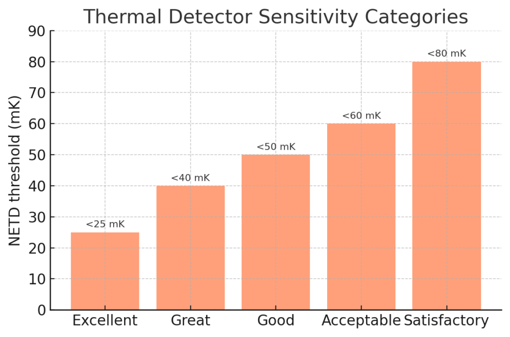
Industry guidance categorizes NETD roughly as follows: <25 mK = Excellent, <40 mK = Great, <50 mK = Good, <60 mK = Acceptable, <80 mK = Satisfactory. Lower NETD cameras can reveal more subtle thermal differences, rendering more shades of gray (or color) in the image for better contrast. For example, a high-end thermal core with NETD <35 mK will produce a crisper image under the same conditions than a budget core with NETD ~60 mK. In inclement weather (rain, fog) or with small temperature deltas, the low-NETD unit maintains clarity and extends detection range, whereas a higher-NETD unit may show noisy, washed-out imagery.
Beware of spec nuances: Ensure the NETD is specified at the standard scene temperature (around 25–30 °C). Some manufacturers quote NETD at 50 °C to make the number look lower. A reputable spec will list NETD at 25 or 30 °C. For instance, a thermal module might advertise “NETD <50 mK @ 30 °C,” meaning it can distinguish 0.05 °C differences at room temperature. Compare like for like, and when possible, seek real-world image examples at low contrast. Also consider that the lens f-number and detector integration time affect effective NETD – faster lenses (low f/#) and longer integration can improve system NETD.
Typical values: Modern uncooled LWIR microbolometers commonly achieve NETD in the 40–60 mK range for affordable models, and ~20–30 mK for premium models (thanks to advancements like smaller pixel pitches and better readout circuits). For context, FLIR’s compact Lepton module has <50 mK sensitivity, while the latest FLIR Boson+ core boasts <20 mK. Lower than 20 mK is usually only seen in cooled MWIR cameras or cutting-edge uncooled research prototypes. As an OEM, choose a module with NETD that meets the demands of your application – e.g. detecting very slight temperature differences (leaks, insulation faults, faint heat signatures) calls for high sensitivity, whereas detecting larger warm bodies (humans, vehicles) in high-contrast environments might work with moderate sensitivity.
Optics: Field of View and Lens Considerations
The optical lens paired with the thermal sensor determines what the module “sees.” Key optical parameters are the focal length (which sets the Field of View, FOV) and the f-number (speed) of the lens. Thermal camera lenses are typically made of special materials like germanium, zinc selenide, or chalcogenide glass that transmit long-wave IR (8–14 µm) radiation. As an OEM buyer, you may have options to select different lenses for a given core, or request a custom lens to suit your needs.
-
Field of View (FOV): This is the angular width and height of the scene captured by the sensor, often expressed in degrees. A wider FOV (e.g. ≥45°) covers more area, which is useful for close-proximity work or situational awareness. For example, a wide lens on a handheld thermal imager lets a technician scan a large section of a wall at once for insulation gaps. In contrast, a narrow FOV (telephoto lens, e.g. 6°–12°) is better for long-range observation – it magnifies distant targets (at the expense of covering a smaller scene). In a security context, a narrow FOV thermal module can detect humans at hundreds of meters but would be impractical for close quarters. Choose FOV based on target distance and coverage area: e.g. a 90° lens for a short-range situational camera, vs. a 12° lens for a long-range spotting scope. Some thermal cores offer multiple lens options – Teledyne FLIR Boson comes with horizontal FOV choices from ~4° up to ~92° depending on lens.
-
Lens Focal Length: Often given in millimeters, it’s directly tied to FOV (for a given sensor size/pixel pitch). Common thermal module lenses include 4 mm (very wide), 7.5 mm, 13 mm, 19 mm, 35 mm, 50 mm, etc. A longer focal length yields a narrower FOV and higher optical magnification. Be mindful that if you change the default lens on a module, the device may need recalibration (for focus and flat-field correction) and the detection range will change. Some vendor data or range calculators can predict detection/recognition distances for various lens/sensor combos. For instance, a 19 mm lens on a 640×480 sensor (~12 µm pitch) might give ~32° horizontal FOV and detect a human ~500 m away, whereas a 50 mm lens (~12° FOV) could extend human detection beyond 1 km under the same conditions.
-
F-Number (f/#): This is the lens focal length divided by its clear aperture. A lower f/# (e.g. f/1.0) lens is “faster,” meaning it admits more infrared radiation to the sensor, improving signal strength and potentially NETD. Most thermal modules use fast lenses (f/1.0 to f/1.3) to maximize sensitivity. A high f/# (say f/1.6 or f/1.8) would reduce the energy reaching the detector, effectively raising NETD (dimming the thermal image). When comparing modules, note if one uses an f/1.0 lens vs f/1.2 – the f/1.0 will have an edge in image brightness and sensitivity. However, lower f/# lenses are larger and more expensive, especially for longer focal lengths (e.g. a 100 mm f/1.0 germanium lens is very large and costly). There are practical limits: uncooled LWIR cameras beyond ~250 mm focal length become unwieldy and are often not offered because a cooled MWIR system would be more feasible for such ranges.
-
Focus Mechanism: Simpler thermal modules have a fixed-focus lens (often set to see clearly from some minimum distance to infinity). This eliminates moving parts and makes integration easy, but you sacrifice the ability to adjust focus for very close targets. Higher-end modules or camera cores may support manual focus or even motorized autofocus. Manual or motor focus adds complexity (gears, motors, control interface) but allows the end-user to get a sharp image on targets at various distances – important for hand-held viewers or dual-use cameras. Determine if your application demands adjustable focus (e.g. a thermal inspection camera needing focus from 0.5 m to infinity) or if fixed-focus at a certain depth is acceptable (e.g. a rifle scope that might be parallax-optimized at long range). Many OEM modules come in both fixed-focus and adjustable versions.
Key takeaway: Optics should match your use-case. Ensure the module can be supplied with the desired lens, or that the vendor can provide lens-mount options if you plan to swap optics. Note that the lens and detector together determine the Instantaneous Field of View (IFOV) – essentially the ground sample distance per pixel at range – which in turn affects detection and identification criteria. If unsure, consult the module manufacturer’s lens charts or request their assistance in selecting the right lens for your detection range requirements.
Resolution and Frame Rate
Resolution (the pixel array size of the thermal sensor) and frame rate (the refresh rate of the thermal images) are two fundamental performance specs that often trade off with cost, data bandwidth, and in some cases, regulatory limits.
-
Sensor Resolution: Common thermal module resolutions include 160×120 (QQVGA), 320×240 or 384×288 (QVGA), and 640×480 or 640×512 (VGA). Higher resolutions like 1024×768 (XGA) are emerging in high-end systems. A higher resolution sensor means each thermal image has more pixels, which provides more detail and the ability to resolve smaller or more distant objects. For example, a 640×480 thermal module can identify smaller features or individuals at range better than a 256×192 module, given the same lens. However, higher resolution sensors are more expensive and produce more data to process.
It’s worth noting that in the current market for uncooled thermal OEM cores (as of mid-2020s), 384×288 and 640×512 are the dominant resolutions for performance-oriented applications. According to market data, about half of thermal sensors shipping for the hunting/outdoor market were QVGA (~384×288) and ~38% were VGA (640×480/512) in 2019 – indicating many OEM products opt for one of these. Lower resolution cores (<= 160×120) are used for compact or low-cost devices (like smartphone attachments or basic thermal viewers), while the latest 1024×768 or higher are still niche and costly. When choosing, consider the smallest target size and longest distance you need to resolve. If you need to see human-size objects at say 500 m, a 320×240 might only give a few pixels on target (detection but not recognition), whereas 640×480 could provide recognition-level detail at that distance. Some vendors provide Johnson’s criteria DRI (Detection, Recognition, Identification) distance estimates for their sensors with various lenses– use those as a guide.
-
Pixel Pitch: Resolution goes hand-in-hand with pixel pitch (the size of each detector pixel, in micrometers). Modern uncooled sensors have pixel pitches of 12 µm or 17 µm typically, down from 25 µm a decade ago. Smaller pixel pitch allows more pixels in the same sensor area or a smaller sensor for the same resolution, which can reduce cost and lens size. For instance, FLIR’s Boson uses a 12 µm pitch detector in 640×512, enabling a very small module. One caveat: as pixel size shrinks, optics need to be sharper (higher Modulation Transfer Function) to fully utilize the resolution, and diffraction begins to limit performance when pixel size approaches the wavelength (for LWIR ~10 µm). Today’s 12 µm uncooled sensors are near that diffraction limit for LWIR, so going much smaller (e.g. 8 µm) will require optic innovations. Nonetheless, R&D trends show pixel sizes continuing to decrease – from ~45 µm in 1990 to 12 µm today, with 10 µm and even 5 µm pixel pitches demonstrated in research for the future. As an OEM, you mostly just need to know the pitch to understand lens compatibility (some datasheets specify that the lens is designed for a certain detector size and pitch). It also influences NETD and resolution trade-offs (more, smaller pixels can increase noise if not well engineered).
-
Frame Rate: Thermal modules often come in two frame rate variants: a <9 Hz version (sometimes listed as 8.7 Hz or 7.5 Hz) that is exportable globally without stringent controls, and a 30 Hz or 60 Hz version which offers full-motion video but may require an export license for international sales. Higher frame rates are crucial for applications with motion – e.g. tracking fast-moving objects, UAV surveillance to avoid motion blur, or fluid thermal events. For a helmet-mounted or weapon-mounted scope, 30 Hz is typically the minimum for a smooth user experience (60 Hz even better). For a static sensor monitoring equipment, 9 Hz might be sufficient. Understand the export implications: Under US EAR (Export Administration Regulations), most uncooled thermal cameras above 9 Hz fall under ECCN 6A003 and need licensing for export, whereas <=9 Hz units are ECCN 6A993 and often No License Required to many countries. European export rules similarly distinguish high frame rates under the Wassenaar Arrangement (6A003.c in EU). If you plan to sell globally, you might opt for the 9 Hz model to ease logistics – but keep in mind that low frame rate video is choppy. Some OEMs mitigate this by doing image interpolation or shuttering tricks, but it’s not the same as true high frame rate capture.
In addition to frame frequency, check if the module supports windowing or analog video output frame rates. Some cores can output 60 Hz via analog (composite video) even if their digital interface is limited to 30 Hz. Others might allow window-of-interest readout at higher rates (e.g. a 640×480 sensor reading a 640×120 window at a faster rate). For most buyers, the standard options (9 Hz vs 30 Hz) are fixed. So choose based on application and compliance: e.g., a thermal sight for local law enforcement can use 30 Hz freely within your country, but a product aimed at international hunting markets might favor the 9 Hz variant to avoid export red tape.
Image Processing, Output Formats, and SDK Support
Another major decision is whether to get a “raw” thermal module vs one with integrated processing. Thermal sensors inherently output analog signals that need transformation into a human-viewable image (and sometimes temperature readings). Many OEM modules now include some level of on-board image signal processing (ISP) and offer a digital video output or data stream. Here are points to consider:
-
Analog vs Digital Output: Legacy thermal cores provided analog video (NTSC/PAL) which can be convenient for simple integration (just feed to a display or video encoder). Modern modules more commonly output digital data (BT.656, parallel CMOS, USB, Ethernet, MIPI CSI-2, etc.). Ensure the module’s output interface is compatible with your system. For instance, if you want to connect directly to a Linux processing board, a USB or MIPI output is ideal, whereas if you are retrofitting into an analog CCTV infrastructure, you might need analog-out. Some cores do both (e.g. FLIR Tau 2 had analog and digital over different connectors). If the module outputs raw pixel data, you’ll need to apply false-color mapping and perhaps temperature calibration in your software.
-
On-board Processing (ISP): Features like non-uniformity correction (NUC), auto gain control (AGC or histogram equalization for contrast), pseudo-color palettes, digital zoom, and even object detection may be handled on-board by smarter cores. Using a module with a built-in thermal image processor can significantly shorten development time – the module essentially behaves like a finished thermal camera, streaming a ready-to-use video feed. For example, an OEM camera module might output a crisp thermal image with dynamic range adjustments done automatically. In contrast, a basic sensor module could give you 14-bit raw thermal frames that look flat and require heavy processing to be useful. If you have thermal image processing expertise or need custom algorithms (perhaps to measure temperatures accurately, or custom image blending), a raw access module gives flexibility. Otherwise, leveraging the vendor’s ISP (if it meets your needs) can save you from reinventing the wheel of image optimization.
-
Radiometric Data: Some thermal modules are radiometric, meaning they are calibrated to output actual temperature readings for each pixel (or at least allow conversion via known formulas). If your application involves temperature measurement (predictive maintenance, fire detection, body temperature screening, etc.), ensure the module is a radiometric type. Radiometric models often have a shutter for periodic recalibration and might output temperature in centigrade or as 16-bit data that your software converts. For instance, FLIR’s Lepton has a radiometric version that gives measurements. Many OEM cores (FLIR Boson, DRS Tamarisk, Seek Mosaic, etc.) offer radiometric modes. Non-radiometric ones are tuned just for imaging (higher contrast, not as accurate for temp). You can often identify radiometric models by looking for a stated accuracy spec (e.g. ±5 °C) and the presence of a calibration shutter.
-
SDK and Software Integration: A critical consideration for OEMs is the software development kit (SDK) or API provided by the module manufacturer. A good SDK will let you control the camera’s features (like choosing color palettes, initiating a flat-field correction, adjusting gain settings, reading spot temperatures, etc.) and will come with libraries or code samples for common platforms (C/C++, Python, ROS, etc.). Check if the vendor provides SDK support for your target operating system (Windows, Linux, Android). For example, FLIR’s Boson SDK supports a USB Video Class mode and a separate command interface for camera control, and InfiRay or ULIS modules have their own SDKs. If you plan to do onboard image processing with your own algorithms (say for target recognition using AI), consider whether the module can output raw data in a convenient format and if it has enough interface bandwidth to stream that data to your processor. Some modules also support third-party middleware – e.g., drivers for GigE Vision, or integration with programs like LabVIEW, which might be relevant for industrial users.
-
Output Format and Video Compression: Determine if you need the module to compress the video (for transmission) or if you will handle that. Some thermal cores on drones, for instance, output H.264/H.265 encoded video over IP to reduce bandwidth. This is not common on raw OEM modules (which usually output uncompressed frames), but a few integrated solutions might include an encoder. Most likely, if needed, you’ll add an encoder chip or use your processor’s capabilities. Just ensure you can get the frames out in a format suitable for that (e.g. 8-bit grayscale or YUV frames for encoding).
In summary, developers with limited thermal imaging experience should lean toward modules with strong ISP and SDK support, essentially treating it as a black-box thermal camera. Those with specific custom processing needs might choose a more bare-bones module where they can control every aspect (but then must implement NUC, image enhancement, etc., themselves).
Ruggedization and Environmental Specs
Depending on your product, you may need a module that can withstand harsh conditions. Key specs to check:
-
Operating Temperature Range: Many uncooled thermal sensors operate roughly -10 °C to +65 °C (commercial range) or extend to -40 °C to +85 °C for industrial/military grades. Ensure the module covers the extremes it will see in use (e.g. a camera for Arctic use or high-heat industrial monitoring). Note that the sensor self-heats when powered, so extremely cold environments are usually not an issue for function (though battery and display might be). At high ambient temps, microbolometer performance can degrade and additional calibration may be needed.
-
Weather Sealing: The module itself is usually not exposed – your end product’s enclosure will provide IP rating (ingress protection) for water/dust. But if the module comes with a lens, that lens may need a durable coating (e.g. diamond-like carbon coating on germanium to resist scratches and moisture). For outdoor applications, ensure the lens has an appropriate protective window or coating. Also consider how the module will be mounted to maintain seal – e.g., via a sealed lens assembly or a window in front of the module.
-
Shock and Vibration: If integrating into something like a drone, a helmet, or a weapon scope, the module should handle shocks (rated in g) and vibration. Check if the vendor has done MIL-STD-810 tests or similar. For a weapon sight application, recoil resistance is critical (some cores are marketed as “ruggedized” for this). If not, you may need to create a shock-absorbing mount. Uncooled sensors are somewhat delicate (a microbolometer die bonded to a package), but many are robust enough if properly mounted.
-
Power Consumption and Thermal Management: Uncooled modules consume anywhere from ~0.5 W to a few watts. Ensure your design can supply stable power and deal with the heat. If a module runs hot, it could affect its own calibration. Some have thermal throttling or specify that you shouldn’t enclose them without heatsinking. Pay attention to power specs (voltage and current draw) and whether it needs a regulated supply.
-
Physical Size/Weight: For weight-sensitive projects (UAVs, handhelds), note the module’s mass. Compact modules like the FLIR Boson weigh under 8 g (core only), whereas older or larger cores could be 50–100 g with housing. If you’re aiming for a small product, choose a core labeled “micro” or “compact”. Many vendors offer a smaller micro core (with limited features) and a larger full-feature core.
By carefully reviewing these environmental and mechanical specs, you can avoid unpleasant surprises (like a module shutting down in a hot climate, or failing after being dropped). For mission-critical systems, you might also inquire about built-in test (BIT) features – some military-grade cores can self-report if they are within spec, have excessive dead pixels, etc., which can aid in quality control.
OEM/ODM Procurement and Integration Guidance
Purchasing an infrared module for integration involves not just technical evaluation but also logistics and business considerations unique to OEM/ODM relationships. Here we outline what procurement managers and product developers should plan for:
Minimum Order Quantities (MOQ) and Lead Times
Thermal sensors are specialized components often produced in batches. MOQ for OEM thermal modules can vary widely – some manufacturers will sell evaluation units one by one, but for an OEM order (especially with customization), expect MOQs of 50-100 units or more. Higher-end or custom-tuned cores might have higher MOQs or NCNR (non-cancellable, non-returnable) terms. Early in engagement, clarify the supplier’s MOQ and pricing tiers (price per unit often drops significantly at larger quantities).
Lead time is another critical factor. Uncooled microbolometers and lenses aren’t typically off-the-shelf in large volumes; they might have lead times of 12 to 20 weeks or more for volume orders. If your design needs a custom lens or enclosure, add extra time for tooling and lens grinding/coating (possibly another 4–8 weeks). Work closely with the supplier on a realistic schedule: for example, ordering a pilot run of modules for prototype builds, then a larger production batch. Be aware of global supply trends – thermal sensors saw high demand during pandemic fever screening, causing lead time spikes. Also, export license processing (if needed) can add 4–8 weeks, so factor that in if applicable.
NRE (Non-Recurring Engineering) and Customization
If you require any custom modifications to the module (different lens, special firmware features, custom form-factor), the vendor may charge an NRE fee. This one-time engineering cost covers design work, tooling, or calibration specific to your needs. For instance, if you want a module with a unique optical filter (say, a mid-wave bandpass) or a custom board shape to fit your product, NRE could be in the thousands to tens of thousands of dollars. In exchange, you typically get exactly what you need and sometimes exclusivity for a period.
Common customizations:
-
Lens swap or custom FOV. The vendor can factory-fit a different lens or configure the focus to your required range. NRE covers re-calibrating the image correction for that lens.
-
Firmware features. E.g., you want the module to output a specific temperature alarm when it detects over a threshold, or integrate custom on-screen symbology. Some vendors can do firmware mods.
-
Interface changes. For large-volume deals, an OEM might request a different connector or pin-out on the module to better fit their device.
-
Ruggedization. Enhanced sealing, added conformal coating on electronics, or testing to higher standards may incur additional costs.
Always discuss these needs upfront. If NRE is too costly, see if there’s an off-the-shelf configuration that you can adapt to – perhaps using an external adapter board or post-processing in your software to achieve the goal.
Quality Assurance and Testing Milestones
When integrating a new camera module, plan a phased approach:
-
Evaluation Kit: Start with an eval kit or a sample unit to validate core functionality and imaging performance. This often includes a demo board and software to operate the module. Use this to ensure the module meets your expectations for image quality, latency, etc.
-
Prototype Integration: Once you commit, get a few modules (often at full price or slightly discounted for development) to integrate into your prototype devices. At this stage, perform functional tests (does it mechanically fit? electrically interface correctly? software communication works?).
-
Design Validation Testing (DVT): With prototypes built, run through environmental tests and use-case scenarios. Check image quality across operating temperature, test any shock/vibration if relevant. You may discover you need to tweak the mounting (e.g., add a heatsink or damping for the module).
-
Pilot Production and QA: Before full ramp, do a pilot batch (maybe 10–30 units). Work with the supplier on any calibration needed. For example, if each module needs pixel calibration or focus adjustment, define who does that (the OEM or you?). Some suppliers will calibrate each unit if provided specifications. Establish incoming inspection criteria – e.g., you might agree on an acceptable number of dead pixels or a NETD confirmation test on samples. Quality milestones can include a golden sample image test: the supplier provides an image of a standard scene from each module to show it meets spec.
-
Mass Production and Ongoing Support: Ensure the vendor can maintain consistency lot-to-lot. Sometimes, sensor supply can change (e.g. a new detector revision). Maintain open communication and possibly secure a buffer stock if your product demand is continuous. Plan for after-sales support: if an end-user finds an imaging defect, will you be able to get replacement modules quickly? It’s wise to get at least a few spare modules for warranty replacements or future needs, as sensor fabs sometimes discontinue certain models after a number of years.
Document all test procedures – e.g., how you will perform a final QC on your assembled product’s thermal output. Some OEM buyers will run a simple test like imaging a known thermal target (a blackbody or a person at known distance) and verifying the image or temperature reading falls in range. Work with the module supplier to define these if necessary.
Regulatory Compliance and Export Controls
Compliance is not just a legal formality – it impacts product design (for labeling, shielding, documentation) and marketability. Key areas:
-
Electrical/Electromagnetic Compliance: In the US, digital devices (even modules) must comply with FCC regulations for unintentional radiators (FCC Part 15). The thermal module, if it’s a component, might be shielded enough or your enclosure will handle it. But if it includes any wireless (some modules have Wi-Fi or Bluetooth for streaming), then intentional transmitter rules apply. For the EU, CE marking is mandatory for finished products. That usually involves EMC testing (per EN 55032/55035 standards for radiated and conducted emissions/immunity), as well as electrical safety (Low Voltage Directive) if applicable. As an OEM module buyer, ask if the module has been through any pre-compliance testing. Often, you’ll have to do the final device compliance testing yourself, but it helps to know if the module passed EMC in a reference design. The CE mark on your product will signify it meets all relevant directives (EMC, RoHS, possibly REACH, etc.).
-
RoHS (Restriction of Hazardous Substances): Virtually all modern electronic components, especially from reputable suppliers, are RoHS compliant, meaning they limit lead, mercury, cadmium, and other hazardous substances per EU directive. Confirm that the module is RoHS compliant (it likely is, but you should get a certificate). This ensures you can sell into EU and other markets that adopted RoHS. It also is just good practice environmentally – for example, lead-free solder and no cadmium in optics. Some infrared lenses historically had germanium (which is fine) and some exotic coatings – but almost all can be RoHS compliant (there are specific exemptions for optical glass if needed).
-
Thermal Camera Export Regulations: As mentioned under frame rates, thermal imaging devices are dual-use technology often subject to export control. Work with your supplier to categorize the module’s export code. Commonly:
-
ECCN 6A003.b.4.b – covers thermal cameras with frame rate >9 Hz or certain resolutions. These typically require a license for export from the US to all but a few countries.
-
ECCN 6A993.a – covers thermal cameras ≤9 Hz, which can usually be exported as NLR (No License Required) to many destinations (exceptions include embargoed countries or prohibited end-users).
-
In the EU, similar controls exist (category 6 on the EU dual-use list). For example, 9 Hz cameras can often be shipped under a general license, whereas >9 Hz need specific permission.
If you are sourcing from a US supplier like Teledyne FLIR, they will likely have you sign documents about end-use and may not even sell you >9 Hz cores if you’re not US/domestic without a license. If you integrate a controlled core into your product, your product may inherit that control classification. Make sure your logistics and sales team is aware – you might need to inform distributors that an export license is required to ship your thermal product internationally. The penalties for violating ITAR/EAR are severe, so build compliance checks (like end-user statements) into your order process for restricted products.
Some OEM/ODM customers choose ITAR-free or “EAR 6A993” cores specifically to avoid these hassles. For instance, you might specify the 8.7 Hz version of a module for all international models. It’s a business decision weighing performance vs. distribution ease.
-
-
Certifications and Documentation: Ensure you receive from the supplier:
-
Declaration of Conformity or test reports for EMC if available (for your tech file).
-
RoHS compliance certificate.
-
Calibration certificate if radiometric.
-
A data sheet and possibly a product manual for the module – often needed if you will include it in your device manual appendix or technical file.
-
Any required warnings or labels. For example, some shutterless thermal cores require a caution that they should not be used for absolute temperature measurements without calibration. Also, if the module has a laser pointer or rangefinder integrated (some do), you’d need the appropriate laser safety labeling per IEC 60825.
-
-
Standard Disclaimers: Many thermal core suppliers will include disclaimer text such as “This thermal module is intended for integration into a final product. It is not a stand-alone camera.” If you are marketing to certain industries (like security or firefighting), there may be guidelines or standards (e.g., NFPA compliance for firefighter cameras, or ONVIF for security) to consider in the end product – though the module itself won’t be certified to those, your product might need to be.
Staying ahead on compliance will save headaches during product launch. It’s wise to involve your regulatory team early to review the module specs.
Conclusion
Infrared thermal camera modules open exciting possibilities for OEM and ODM product developers – enabling night vision, non-contact temperature measurement, and enhanced vision systems across industries. Making the right selection involves balancing technical performance with integration practicalities and compliance obligations. By understanding metrics like NETD and resolution, choosing optics wisely, leveraging on-board processing where helpful, and planning out the procurement and testing process, you can significantly de-risk your development and deliver a successful thermal imaging product.
If you’re ready to take the next step with thermal integration, consider engaging with a partner experienced in OEM thermal solutions like Gemini Optics. As a specialized thermal imaging and optics OEM/ODM provider, Gemini Optics can assist in selecting and customizing modules for your exact needs.
-
Request a Thermal Module Demo: Get in touch to see live image demos from various camera cores and evaluate which meets your application requirements. (Contact our sales team to schedule a demo or to receive sample images.)
-
Download the Technical Data Sheet: For detailed specifications on our available thermal modules and lenses, download our product data sheets for a comprehensive feature comparison.
-
Integration Consultation: Need guidance on embedding a thermal module into your device? Our experts offer free initial integration consultations – we’ll help you outline optics selection, interface design, and compliance steps to accelerate your development.
We hope this guide has empowered you with knowledge to select the ideal infrared camera module. The world of thermal imaging is advancing rapidly, and with the right module choice, you’ll be on the cutting edge of this technology. Feel free to reach out to Gemini Optics for any further questions or support on your thermal imaging projects.