If your team’s thermal footage looks great in the lab but struggles at distance in the field, the problem is rarely one setting. Range is a system outcome shaped by optics, sensor physics, firmware, and even how your pilots or guards operate. This guide distills seven practical tweaks you can apply to a thermal camera core, a drop-in thermal camera modules, or a full thermal imaging camera module to extend practical detection range—without turning the payload into a brick or breaking operator workflows. We’ll lean on well-established optics math and industry conventions so your choices are defensible in design reviews and procurement meetings.
Table of Contents
ToggleUnderstanding detection range, in plain language
Thermal range planning boils down to how many pixels you put across a target at the distances that matter, and whether those pixels carry enough contrast to rise above noise and compression. Two related ideas drive most decisions. First, field of view (FOV) sets how wide a scene you see for a given focal length and sensor size; the classic rectilinear relationship FOV=2arctan(x/2f)\mathrm{FOV}=2\arctan(x/2f)FOV=2arctan(x/2f) is the backbone of lens calculators. Second, instantaneous field of view (IFOV) describes angular size per pixel (≈ pixel pitch ÷ focal length), which you can use with “Johnson-style” planning rules to estimate detection, recognition, and identification distances for common targets.
Range never lives on math alone. Signal-to-noise depends on detector NETD and optics f-number; image sharpness follows the lens and system MTF; and long paths through humid air can sap contrast through attenuation. Those realities explain why two builds with the same nominal HFOV perform differently in wind, humidity, or at dusk; each element in the chain modifies how much contrast survives to your display or encoder.
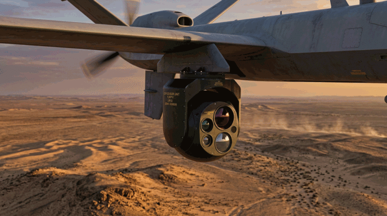
Where range matters most: security vs. UAV
For fixed security, you usually care about humans near fences and vehicles on approach lanes. Wider FOVs reduce camera count and provide context for analytics, but if your longest approach never exceeds 400 m, a moderate telephoto often pays back immediately because it puts enough pixels on target to separate a person from a hot background. In UAV work, altitude and stability tilt the trade-off. A 20–35° HFOV is a productive “search” band at ~100–120 m AGL because it maintains a wide ground swath without starving the scene of pixels; once you narrow into single-digit HFOVs, tiny gimbal motions smear more than a pixel and pilots work harder to keep targets in frame. These differences will color the seven tweaks below, but the physics is shared.
The seven tweaks
1) Right-size focal length to pixel-on-target, not to “max zoom”
The fastest way to real range is to choose focal length from pixels-on-target rather than from “what looks tele.” Use your sensor’s pixel pitch and focal length to estimate IFOV in milliradians (mrad), then apply Johnson-style thresholds (≈2 px detect, ≈6–8 px recognize, ≈12–14 px identify) to your critical target width. For human torsos (~0.5 m) or vehicles (~2.3 m), this gives planning-grade distances you can defend in a review. Remember: this math is a starting point—final numbers depend on NETD, contrast, motion, and atmosphere.
Quick planning table (640×512 @ 12 µm, IFOV ≈ 0.012 mm / f):
| Focal length | IFOV (mrad) | Human detect (~2 px) | Recognize (~6 px) | Identify (~12 px) |
|---|---|---|---|---|
| 19 mm | 0.632 | ~396 m | ~132 m | ~66 m |
| 25 mm | 0.480 | ~521 m | ~174 m | ~87 m |
| 35 mm | 0.343 | ~729 m | ~243 m | ~122 m |
These ranges are order-of-magnitude estimates to prove a point: picking 25 mm over 19 mm is not “a little more zoom”—it’s a ~30 % bump in detection distance for a human-sized target at the same core. The FOV math that underpins this table is the standard 2arctan(x/2f)2\arctan(x/2f)2arctan(x/2f) relationship.
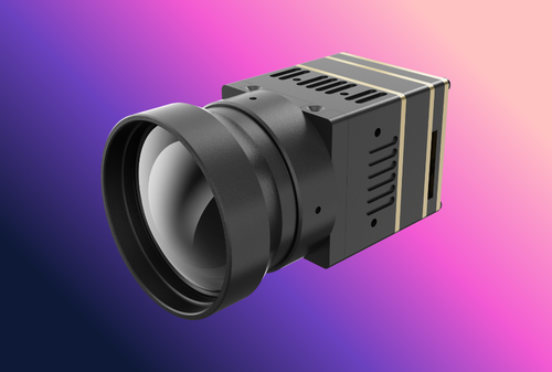
2) Use faster glass where it counts—but price the weight and stability
A lower f-number (f/1.0 vs f/1.2) brings more energy to the detector, improving SNR and helping faint targets survive post-processing and compression. The catch is mass and diameter: germanium scales quickly, increasing payload weight, moment of inertia, and wind sensitivity. On a mast or large gimbal this is manageable; on small UAVs, a lighter f/1.2 25 mm may outperform a heavy f/1.0 35–50 mm once you count flight time and stabilization. Treat lens choice, gimbal torque, and platform endurance as one system decision. The “more light per pixel” logic is straight from imaging basics and MTF/SNR behavior.
3) Nail focus and preserve MTF from window to display
Range dies first at focus. A slightly defocused telephoto at 300 m looks “soft” even if your math is perfect. Lock predictable hyperfocal positions for fixed sites, validate at real temperatures, and avoid frequent refocus events that confuse analytics. In the air, a lightweight focus motor with a sensible step size is worth its grams because it lets pilots keep detail when altitude changes. Keep the optical path clean: a scratched or uncoated window reduces contrast at mid-high spatial frequencies; poor mounts invite micro-shake. Since range hinges on contrast transfer, protecting system MTF from lens through mechanics is non-negotiable.
4) Tune AGC/gain for stable contrast, not “wow factor” histograms
Auto-gain control that chases every bright roof vent or setting sun will compress the grayscale where your targets live. Start from mission presets: “security/perimeter” should favor stable background and mid-tones for people and vehicles; “search/inspection” can bias toward small hot spots. Pair AGC with non-uniformity correction (NUC/FFC) at appropriate intervals; running too often in flight risks missed moments, but neglecting NUC lets fixed pattern noise chew SNR and perceived detail. NIST’s work on display quality underlines how quickly low SNR hides signal; your gain and NUC policies directly affect the operator’s ability to distinguish a target near the noise floor.
5) Reduce noise the right way: temporal filtering before sharpening
When distance pushes scenes toward the noise floor, temporal averaging/denoise can legitimately extend practical detection range—if you apply it before edge enhancement. Start with a modest temporal filter to tame frame-to-frame speckle, then apply restrained sharpening to recover edges. Invert that order and you will amplify noise into fake edges and ringing, making distant targets harder to discern. This sequencing reflects standard imaging practice: SNR-first, then detail restoration, because sharpening operates on contrast that noise otherwise contaminates.
6) Stabilize the image to protect “one-pixel truth”
At long distances, a one-pixel smear destroys the very advantage you bought with focal length. For fixed sites, ensure mounts don’t resonate in wind and that pan-tilt units are balanced and tight. In UAV use, gimbal tuning and pilot SOP matter as much as the lens: avoid narrow HFOVs during turns, hold hover for clarifying shots, and evaluate electronic image stabilization only as a light assist, not a substitute for mechanics. The physics here is ordinary but unforgiving: even tiny angular oscillations translate to multiple pixels of motion at telephoto, which your operator perceives as “softness.” (In other words, keep the scene still so MTF stays meaningful.)
7) Preserve detail through the encoder and palette choices
You can throw away range after capture if the bitrate, compression, or palette undermine small contrasts. For evidence or long standoffs, raise bitrate rather than over-sharpen; aggressive quantization smooths low-contrast detail that would otherwise add up over a few frames. Choose operator-tested palettes (white-hot, black-hot, and one color map) so targets pop against typical backgrounds without cognitive overload. None of this replaces optics, but it prevents the pipeline from erasing gains you paid for upstream. The principle is simple: the chain is only as strong as the weakest link, and compression is very good at discarding what looks like “insignificant” contrast to a generic encoder.
Security vs. UAV: how the tweaks play out
Consider a refinery perimeter with long approach corridors. Picking 35 mm over 25 mm on a 640×512/12 µm core can move you from “detect” to “recognize” for a human at the far end of the lane, especially once you combine a modest temporal denoise and a stable pan-tilt. The budget penalty often lands on the mount: heavier optics mean higher wind sensitivity, so you plan for a sturdier head and better cabling. In flight operations, a 19–25 mm lens at 100–120 m AGL keeps a healthy swath; pilots can then pause and use a 35 mm “clarifier” only when the gimbal is truly steady. Swapping the order—flying narrow all the time—usually produces fewer finds and more re-flights because jitter smears the very pixels you tried to buy with focal length.
Integration and OEM/ODM considerations you shouldn’t skip
Lens choice becomes easier once you lock the core and video path. Many teams take raw or digital video from the thermal imaging module and feed a compact encoder for network streaming, keeping firmware-level controls on gain, NUC, palettes, and focus in a tidy UART or CAN interface. Document presets as part of your SDK so the same payload behaves predictably on different airframes or mast tops. Finally, protect SNR and MTF mechanically: isolate vibrations near the optical path, specify coated windows, and add a low-cost sacrificial window for dusty sites so you don’t degrade contrast in month two.
If you’re standing up a new product line, consolidate lens variants into a single BOM family with shared software and test artifacts. That way, your 25 mm “search” and 35 mm “clarify” units differ only in optics and focus mechanics—everything else ships identical, which saves cycles in QA and support.
Cost, compliance, and lifecycle ROI
It’s tempting to look at lens price in isolation. But a heavier, faster telephoto nudges gimbal class, cabling, and power budgets; it can also force UAV battery swaps earlier in a shift. Conversely, a moderate 25 mm lens that permits a higher flight speed can reduce OPEX even if you occasionally pause for a clarifying hover. On the compliance front, thermal alone is straightforward; when you pair with laser pointers or rangefinders, budget for Class 1 safety reviews and labeling early so you don’t re-spin housings later. The ROI test is pragmatic: if a tweak materially lowers missed detections, false alarms, or re-flight rates, it pays for itself quickly—often faster than spec-sheet gains suggest—because operators stop fighting the system and start trusting it.
Partnering and next steps
If you want an eyes-open recommendation tailored to your sites or airframes, our engineering team can model HFOV/IFOV and Johnson-style distances against your targets, altitudes, and stability limits, then translate those into a short list of lens and preset options you can actually procure this quarter. Explore our configurable Thermal camera module for sensor and lens pairings, dive into practical checklists on Thermal camera module integration, align organizationally with our OEM/ODM Partner Program, and when you’re ready to see numbers for your mission, contact us for a 30-minute optics consult.
FAQs
Does digital zoom increase range?
No. It crops the sensor; it does not change IFOV. Use it to frame or to assist an operator briefly, but treat optical focal length and stability as your real range levers.
Is f/1.0 always better than f/1.2?
It collects more energy and can improve SNR, but the added size and mass can hurt stability or endurance. If a lighter lens lets you fly longer or hold steadier, it may win on real detections, not just on paper.
How often should I run NUC/FFC?
Enough to prevent fixed-pattern noise from eroding SNR, but not so often that you miss moments. In UAV overwatch, tie NUC to hover pauses; in fixed security, schedule during lulls or via temperature-based triggers. The aim is stable contrast, not the flattest histogram.