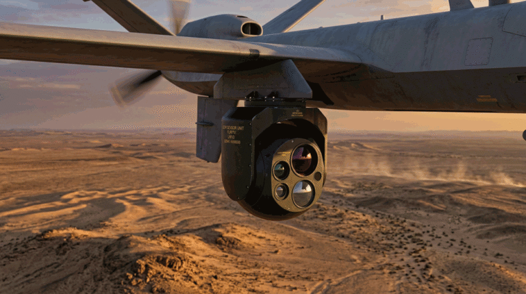
A thermal imaging module succeeds or fails not on the datasheet alone but on integration: power integrity, thermal behavior, optics alignment, mechanical stability, encoder choices, mission geometry, and system timing. This top-checklist unpacks the seven risks that silently cap detection/recognition range and operator trust—and shows exactly how to avoid them in your next UAV, security PTZ, or embedded vision product.
Table of Contents
ToggleHow buyers and engineers actually evaluate a thermal imaging module
Before anyone opens a PO, three moments happen—fast:
- Fit/No-Fit scan (≤60 s). Resolution/FOV family, interfaces, frame rate, size/weight/power.
- Risk review. NETD at real fps/f/#, uniformity policy (shuttered/shutterless), latency/bitrate, temperature drift.
- Proof. Sample clips at mission ranges, MRTD/MTF plots, acceptance tests that QA and finance can sign.
This article is organized the same way: practical failure modes → visible symptoms → quick tests → durable fixes.
Risk 1 — Noisy Power & Grounding (EMI/EMC) → Banding, FPN, Reboots
What goes wrong
Switching regulators, long harnesses, and shared grounds inject ripple and broadband noise into analog stages and the detector bias rail. On bench, the image looks fine; in the air or on a tower with motors and radios active, you see horizontal banding, striping, or even random reboots under throttle or PTZ acceleration.
How it kills range
Noise lifts the apparent NETD floor and obscures small ∆T features at long distance; striping mimics fixed-pattern noise (FPN) and fatigues operators.
Fast diagnostics
- Log image RMS noise vs. input ripple while stepping motors/radios.
- Scope the module input at >100 MHz bandwidth; look for switcher fundamental + harmonics.
- Flip a dummy load on/off near the camera to provoke supply dip and watch for frame drops.
De-risk checklist
- Isolate camera power rails; use Pi filters (L-C-L) with low-ESR capacitors close to the module.
- Keep return paths short; star-ground sensitive analog returns.
- Shield twisted pairs; separate power and high-dv/dt motor phases.
- Add TVS at connectors, common-mode chokes on data lines; verify ESD/surge to your certification level.
- Document a PSU spec: ripple ≤X mVpp (20 MHz BW), step load recovery ≤Y µs, voltage droop ≤Z%.
What to publish/specify
“Requires 5–12 V with ripple ≤30 mVpp (20 MHz BW); recommended input Pi filter 10 µH/22 µF/10 µH; chassis to logic ground bonded at camera only.”
Risk 2 — Thermal Design & Calibration Drift → “Looks fine cold, mushy when hot”
What goes wrong
The focal plane array (FPA) warms or cools with airflow, sun load, or gimbal position. Offsets/gains drift, and if your NUC (non-uniformity correction) policy is naïve, the image gains striping/ghosts or loses faint contrast after 10–20 minutes.
How it kills range
Drift raises effective noise and lowers mid-frequency contrast; recognition collapses even with “good NETD.”
Fast diagnostics
- Record 30 min of video at steady scene while logging FPA temperature; plot residual FPN vs. ∆T.
- Test three airflows: still air, forward flight, tailwind—note how fast drift appears.
- Compare shuttered vs shutterless behavior; measure freeze time and post-calibration settling.
De-risk checklist
- Use hybrid NUC: shutterless continuous + scheduled shutters only at takeoff/landing or operator command.
- Thermally decouple the camera from hot frames; add a low-mass heat spreader where needed.
- Provide FPA temp telemetry; set a ∆T threshold (e.g., 8 °C) that prompts a quick calibration during hover.
- Store per-lens NUC tables if your product ships with multiple objectives—glass matters.
What to publish/specify
“Default NUC: shutterless continuous; shutter on ground or by operator. Freeze ≤0.8 s; residual FPN ≤0.4% on flat field across ±10 °C FPA delta.”
Risk 3 — Optics Stack & Focus Tolerance → MTF Loss You Can’t “Sharpen” Away
What goes wrong
Back-focus error, window wedge, mis-torqued lens mounts, or cheap protective windows drop MTF in the spatial-frequency band that carries recognition/ID. Operators see soft edges and shimmering mid-tones; engineering “adds sharpening” and makes halos.
How it kills range
Pixels without contrast are not usable pixels. Johnson math assumes contrast survives; soft optics erase your recognition advantage.
Fast diagnostics
- Measure MTF50 on a bar chart at your critical range (e.g., 300–400 m).
- Shoot the same scene with window in/out to quantify window loss; check for veiling glare.
- Check focus repeatability across temperature; mark the torque spec and witness the screws.
De-risk checklist
- Use coated windows (e.g., DLC) sized to avoid vignetting at the widest FOV; specify wedge ≤X mrad.
- Lock focus with a fine thread and set a torque; add anti-rotation features.
- If fixed-focus, select a hyperfocal distance that meets your corridor/altitude targets.
- Publish an MTF plot at shipped f/# and a focus SOP for field service.
What to publish/specify
“35 mm f/1.0 lens: MTF50 ≥0.3 at 20 lp/mrad; back-focus tolerance ±25 µm; window wedge ≤1 mrad; repeatability ±5 µm across −10…+50 °C.”
Risk 4 — Mechanical Vibration & Gimbal Jitter → Motion Blur Eats Recognition
What goes wrong
High wind, prop wash, or PTZ backlash introduces micro-jitter. Narrow FOV amplifies motion; if a shutter moves, the impulse rings through the mount. Frames look “smeared,” especially at 50–60 fps during hover or long zooms.
How it kills range
Motion blur destroys mid-to-high spatial frequencies—the part of the image your observer needs for recognition/ID.
Fast diagnostics
-
Log gyros/accelerometers and overlay with frame sharpness score.
-
Test narrow HFOV during gusts; quantify blur with an edge-spread metric.
-
If using a mechanical shutter, measure post-calibration settling time to full MTF.
De-risk checklist
-
Tune gimbal PID for narrow FOV; constrain maximum zoom unless hover stability ≥ threshold.
-
If shuttered, schedule events only on ground or during stable hover.
-
Prefer shorter focal lengths enabled by smaller pixel pitch for the same FOV (lighter, less jitter-sensitive lens).
-
Raise exposure priority during hover; lock frame timing to reduce smear.
What to publish/specify
“Gimbal blur budget: MTF50 drop ≤10% in 8–12 m/s wind at 25 mm; post-shutter recovery ≤1.0 s; recommend hover for HFOV <12°.”
Risk 5 — FOV/IFOV Mismatch to Mission → “Wrong Lens, Wrong Results”
What goes wrong
Teams choose resolution by habit (e.g., “640 is best”) and forget IFOV. A 640 with a too-wide FOV still puts too few pixels across the target at range; a 256 with an ultra-narrow lens is twitchy and unusable except in perfect hover.
How it kills range
Under-sampling caps recognition/ID no matter how good NETD or optics are; over-narrow FOV lowers search efficiency and increases operator workload.
Fast diagnostics
-
Compute pixels across a 0.5 m torso at your distances; check Johnson thresholds for recognition (≈8 px).
-
Compare two builds at equal IFOV rather than equal resolution; review real clips in the worst weather month.
De-risk checklist
-
Define two FOV families per platform: a search FOV (≈20–35°) and a corridor/clarify FOV (≈8–15°).
-
Use 12 µm pitch where possible to shorten focal length for the same FOV (lighter optics).
-
Write your spec as task@distance (“recognize 0.5 m at 350 m”) rather than “we want 640.”
What to publish/specify
“Pixels-on-target examples: 0.5 m torso @350 m → ~9–10 px with 12° HFOV (640/12 µm @50 mm); same at 35 mm (12 µm) yields ~7 px.”
Risk 6 — Encoder, Bitrate & Latency → Codec Eats the Detail You Paid For
What goes wrong
Streams look clean in daylight but wash out at distance or at night. Aggressive compression, long GOPs, or unstable frame pacing remove faint edges. High end-to-end latency makes gimbals hard to steer.
How it kills range
Tone mapping + compression can crush mid-tones and smear edges—operators miss targets; analytics produce false positives.
Fast diagnostics
-
Compare lossless/visually lossless vs your shipping encode at 8 Mb/s, 12 Mb/s, 20 Mb/s on a distant target.
-
Measure glass-to-glass latency with a flashing LED rig; note variance (jitter).
-
Test Search vs Overwatch presets on long humid nights.
De-risk checklist
-
Ship two presets: Search (8–12 Mb/s, gentle tone curve) and Overwatch (14–20 Mb/s, preserved mid-tones).
-
Stabilize frame pacing; avoid over-sharpening halos.
-
If link bandwidth varies, prioritize bitrate floor over high fps for long standoffs.
What to publish/specify
“H.265 Main; latency 140–180 ms @60 fps; presets: Search 10–12 Mb/s, Overwatch 16–20 Mb/s; tone curve ‘Night-Mid’ default.”
Risk 7 — Time Sync, Metadata & SDK Surprises → “Great Image, Wrong Millisecond”
What goes wrong
Video looks fine but timestamps drift; overlays don’t align with gimbal azimuth; analytics can’t correlate frames with GPS/PPS. NUC events, palettes, and gain settings aren’t logged, so field anomalies can’t be reproduced.
How it kills range
Evidence value and analytics confidence drop; control loops (slew-to-cue) lag; multi-sensor fusion fails.
Fast diagnostics
-
Verify PPS/PTP lock; measure timestamp drift over 30 min.
-
Interleave MAVLink (or your bus) with camera metadata; confirm azimuth/elevation in the video container.
-
Trigger a NUC; check that the event is in both video metadata and the SDK log.
De-risk checklist
-
Expose a stable SDK surface:
set_palette(),set_gain(),nuc_mode,nuc_trigger(),get_fpa_temp(),get_timestamp(). -
Support PTP (IEEE 1588) or PPS; include camera-origin clock and stream time.
-
Record NUC events, FPA temp, encoder preset, and palette as metadata.
-
Provide sample code to set NUC and encoder in 10–12 lines.
What to publish/specify
“Time sync: PTP v2 or PPS; timestamp drift ≤1 ms/min; video carries KLV metadata (lat/lon/alt, gimbal angles, NUC state).”
A compact acceptance-test table you can paste into a PRD
| Category | Test & Limit | Notes |
|---|---|---|
| Power/EMI | Ripple ≤30 mVpp (20 MHz BW); no banding under full motor/radio load | Scope at module; record image RMS |
| Thermal/NUC | Residual FPN ≤0.4% across ±10 °C FPA; freeze ≤0.8 s, ≤1 per 20 min | Hybrid NUC profile |
| Optics/MTF | MTF50 ≥0.3 at 20 lp/mrad; focus repeatability ±5 µm | Validate with shipping window |
| Jitter/Blur | MTF50 drop ≤10% at 25 mm lens in 10 m/s wind | Log IMU + sharpness |
| IFOV/DRI | 0.5 m torso ≥8 px @350 m in narrow FOV | Show calculation & clip |
| Codec/Latency | Glass-to-glass ≤180 ms; Search ≥10 Mb/s; Overwatch ≥16 Mb/s | No oversharpening halos |
| Time Sync/Meta | Drift ≤1 ms/min; NUC events & FPA temp in KLV | PTP or PPS lock |
Two mini case studies—what actually decided the win
Maritime patrol (uniform horizons). The team shortlisted three modules with similar NETD. The winner published a hybrid NUC with a single-image fallback for low-diversity scenes, logged NUC events, and provided a clip recorded at Overwatch bitrate. Striping stayed below the PRD limit on hot, humid evenings.
Refinery corridor (long standoff, windy). A vendor “won” on resolution but lost on MTF after gusts. The competitor with a shorter, stiffer 12 µm lens held contrast; a 384 build beat a shaky 640 in recognition probability at 400 m.
How to present the “Top-Checklist” on your product page
-
Hero: one-line promise and the two encoder presets.
-
Nine Spec Block (from your previous article) and a one-screen Top-Checklist summary.
-
Clips: three 10-second videos—search swath, narrow clarify, uniform horizon stress.
-
Engineering Notes: one link to deeper docs; no PDF walls.
-
CTA: one paragraph, four internal links (each used once).
FAQs (concise, integration-focused)
Do I need shutterless NUC for UAVs?
In most missions, yes for continuity; keep a hybrid fallback for radiometry and uniform scenes.
Is 640 always better than 384?
Only if IFOV and MTF are preserved and your gimbal/bitrate support it. A tuned 384 with a shorter lens often wins in wind.
Why do lab NETD numbers not match field results?
Because power noise, thermal drift, motion blur, and compression raise the effective floor in practice.
Can I fix soft images in post with sharpening?
Sharpening cannot restore MTF lost to defocus or blur; it adds halos and operator fatigue.
Call to Action
If you’re integrating a thermal imaging module and want field results that match the datasheet, we’ll audit your power, thermal path, optics mechanics, encoder presets, and timing, then return an acceptance pack with limits you can paste into the PO. Start with our Thermal camera module, dive into Thermal camera module integration, plan mixed builds via Laser Rangefinder Modules, align with the OEM/ODM Partner Program, then contact us to schedule a 30-minute integration workshop.