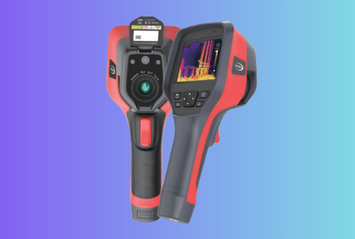
Choosing the right industrial thermal imaging camera is not just a matter of reading a few specs on a datasheet. OEM product managers, integrators and distributors have to match each industrial thermal imaging camera platform to real inspection routes, safety requirements, uptime targets and margin expectations. This guide walks through the key decisions—from detector, lens and FOV to firmware, compliance and business model—so you can build an industrial thermal imaging camera lineup that sells reliably, protects your brand and keeps your customers’ plants running safely.
Table of Contents
ToggleWho this is for: OEM/ODM product managers, systems integrators, and distributors who must choose, integrate, and support industrial imagers across electrical, mechanical, HVAC, utilities and building diagnostics programs.
What you’ll learn: The practical difference (device vs. workflow), how industrial IR cameras cut 30–60 minutes from inspection routes, what to spec, how to integrate quickly, and how to defend the purchase with crisp acceptance criteria and ROI.
Executive Summary
-
- “Thermal camera” = device; “thermal imaging” = device + workflow. Choose hardware that ships with radiometry, one-click PDF/CSV, and a boringly reliable desktop tool. That’s what shortens routes.
-
- Buy IFOV and NETD, not pixels alone. For 0.7–1.5 m work on lugs, bearings, and coil fins, 384×288, ≤50–35 mK NETD with manual focus is the true workhorse.
-
- Standardize a three-screen UI. Scan → Detail (ΔT with span lock) → Report (paired thermal+visual, voice note, asset ID). Anything else belongs behind a long-press menu.
-
- Compliance and export aren’t afterthoughts. If you combine an imager with ranging or illumination, confirm IEC 60825-1 Class 1 and local notices; for electronics, plan CE/FCC/RoHS.
-
- Acceptance beats argument. Use a small heated target at set distances to verify IFOV and accuracy; track time-to-actionable image and % work orders with PDF as go-live KPIs.
Use Cases & Buyer Scenarios
Scenario 1 — Electrical maintenance (switchgear & MCCs)
A reliability team needs to detect hot lugs, loose joints, busbar splice issues, and load imbalance. The industrial thermal camera must resolve 5–10 mm targets at ~1 m, label ΔT vs. healthy phase, and export a one-page PDF that attaches cleanly to the CMMS work order. A handheld industrial thermal camera with manual focus, ΔT macro, and radiometric JPEG is ideal.
Helpful internal deep-dives you might reference later: Thermal camera module.
Scenario 2 — Mechanical routes (motors, bearings, gearboxes)
Technicians trend drive-end vs. non-drive-end temperature, housing fin cooling patterns, and seal lines. They need fast glass, short minimum focus distance (MFD), and macro capability for small caps. ΔT against ambient is logged monthly. A radiometric industrial infrared camera with a short MFD and a simple span-lock button avoids re-shoots.
Scenario 3 — HVAC & building envelope
Contractors search for duct leakage, coil ΔT, insulation voids, and window/door losses. Wider FOV helps walk large surfaces; dew-point proximity (ambient + RH) reduces arguments about condensation. Paired thermal + visual captures with brief notes make client proposals easier.
Spec & Selection Guide (the heart)
Below we define the parameters that actually change your route time and evidence quality.
Core definitions (plain English)
-
- NETD (Noise-Equivalent Temperature Difference) — the smallest temperature delta the sensor can distinguish from its own noise (mK; lower = better). Aim ≤50 mK for fleets; ≤35 mK where subtle deltas matter.
-
- IFOV (Instantaneous Field of View) — angular size of a single pixel (mrad). Spot size ≈ distance × IFOV. Ensure ≥3×3 pixels cover your smallest target.
-
- Radiometric image — each pixel stores temperature; you can change palette/span later and still measure. Essential for trending and audits.
-
- FOV/HFOV — field of view (horizontal). 27–45° is practical for plant rooms; narrower tele lenses help at distance.
-
- Accuracy — typically ±2 °C or ±2% (whichever greater) for professional devices.
-
- Temperature range — most work happens in −20…150 °C; keep a 100…550/650 °C span for process hot spots.
-
- Emissivity (ε) — how efficiently a surface emits IR (0–1). Painted steel ≈0.95, oxidized copper ≈0.78; bright aluminum often needs a tape dot.
Comparison Table — what to weigh first
| Parameter | Practical choices | Why it matters | Trade-offs |
|---|---|---|---|
| Detector & NETD | 256×192 / 384×288 / 640×512; ≤50–35 mK | Spatial detail + sensitivity; fewer re-shoots | Higher res = cost + compute + power |
| Lens & IFOV | Normal (≈24–35° HFOV), macro option | Resolves 5–10 mm lugs at 0.7–1.5 m | Tele helps distance; hurts room coverage |
| Focus | Manual or hybrid AF | Crisp small targets; faster acceptance | Fixed focus is simple but soft up close |
| Radiometry | Yes (RJPEG or equivalent) | Proof, PDFs, CSV trending | Larger files; needs desktop tool |
| Range & Span | −20…150 °C and 100…650 °C | General + process work | Range switching should not reset your span |
| I/O & SDK | USB-C (UVC), Wi-Fi, CSV/PDF, simple SDK | Fast ingestion, fleet scripts | More options can complicate UI |
If/Then quick rules
IF smallest target ≤5 mm at ~1 m
THEN pick 384×288 or 640×512 + manual focus + macro clip-on
ELSE 256×192 with good optics is fine
IF you must prove ΔT in work orders
THEN insist on radiometry + one-click PDF/CSV
IF rooms are tight and wide surfaces dominate
THEN prefer 35–45° HFOV; keep tele only for special routes
IF operators wear gloves or work in cold
THEN require hot-swap batteries, large buttons, and runtime at −10 °C
IF you plan to overlay distance or fusion later
THEN leave UART/USB spare and consider Laser Rangefinder Module alignment space
Integration & Engineering Notes
Electrical & Interfaces
-
- USB-C/UVC for live viewing and mass storage is the least-friction bridge to PCs.
-
- UART helps when embedding the camera core into a host; log device ID, time, emissivity, ambient, and ROIs with each frame.
-
- CAN or RS-485 can ride long cable runs in harsh environments; keep baud/termination consistent with PLCs.
-
- SDK: favor simple APIs that output RJPEG → CSV/PDF; avoid lock-in proprietary viewers only.
-
- MAVLink (or UDP JSON) makes sense for robots/UAVs; keep message sets narrow (timestamp, pose, ΔT, alarms).
Rule of thumb: if integration will take engineers more than a week, start with “files-in-folder” export from the desktop tool and automate the ingest in your CMMS. It scales surprisingly far.
Optics & Mechanics (mounting, alignment, sealing, recoil/vibration)
-
- Mounting: 1/4-20 thread plus a short handle/tripod covers 80% of field use; use anti-rotation pinning for permanent rigs.
-
- Sealing: design for IP54 minimum; gaskets around lens barrels are failure points—choose field-replaceable seals.
-
- Shock/Vibration: validate to 2 m drop on concrete; run 5–500 Hz sine/random on fixtures.
-
- Thermal drift: perform a NUC (non-uniformity correction) after cold starts and big ambient swings; expose the button, don’t bury it.
Firmware/ISP/Tuning (AGC, fusion, filtering, ranging algorithm)
-
- AGC (auto-gain control): keep two modes: Scan (auto, fast) and Detail (locked span). Techs must switch in one tap.
-
- Filtering: oversharpening creates fake edges; provide a “Detail/Comfort” toggle and remember the choice.
-
- Fusion: if you add visible light or range overlays, calibrate both paths in the jig and stamp a calibration checksum.
-
- On-device math: ΔT against a reference box, isotherms (>, <) with audible cues, and dew-point proximity if an RH/ambient sensor is present.
Testing & Validation (bench → field, acceptance criteria and metrics)
Bench IFOV check: put a 5 mm heated dot at 0.5/1.0/2.0 m; verify the dot spans ≥3×3 pixels and the temperature reading is within ±2 °C or ±2% vs a contact probe.
Field pilot (2 weeks): three crews, three routes. Track:
-
- Time-to-actionable image median (goal <90 s).
-
- % work orders with attached PDF (goal ≥80%).
-
- First-time fix rate (improve ≥10%).
Pass gate: all three KPIs hit by week 4; radiometric files open in your tool and in the customer’s viewer.
Compliance, Export & Certifications
Even if your industrial infrared camera is “just” a passive imager, your system often contains radio modules, chargers, batteries, or optional rangers/illuminators. Cover these early:
-
- IEC 60825-1 (laser safety) — if you integrate a ranging/pointing laser, ship Class 1 accessible emission limits (AEL) in normal operation, label apertures, and place the compliance mark on the housing.
-
- FDA Laser Notice No. 56 (US) — harmonizes laser classification with IEC for US entry; coordinate with your importer.
-
- CE (EU) — typically EMC, LVD, RED if radios, and RoHS for substances; maintain a technical file and DoC.
-
- FCC (US) — radiated/conducted emissions for products with intentional/unintentional radiators.
-
- WEEE/RoHS — plan take-back and material declarations with your EMS.
-
- Dual-use/export — thermal cores above certain frame rates or resolutions can trigger controls; confirm HS codes and destination-specific rules early.
Record-keeping: retain BOM, calibration certificates, and test reports; your distributor will ask during onboarding.
Business Model, MOQ & Lead Time
-
- Samples: 2–3 weeks for off-the-shelf devices; 4–8 weeks for branded private-label pilots (colorway, UI strings, report templates).
-
- MOQ: typical 50–200 units for private label; higher if you change plastics; 10–20 for “integration kits.”
-
- MP cycle: 8–12 weeks after pilot approval and artwork lock; buffers for certification if you add radios/lasers.
-
- Kit-packing: standardize batteries, macro clip-on, short handle/tripod, soft case, and a laminated two-minute workflow card.
-
- Docs: supply editable PDF templates, CSV mapping for CMMS, and a calibration certificate per unit.
Distributor ROI sketch (illustrative)
| Assumption | Value |
|---|---|
| Street price (workhorse) | $3,900 |
| Distributor margin | 22% |
| Sell-through per rep / month | 4 units |
| Monthly gross profit / rep | ≈ $3,432 |
| Demo kit & training cost (amortized) | $250 / month |
Even modest sell-through funds dedicated reliability workshops that drive upsells into accessories and service plans.
Pitfalls, Benchmarks & QA
Seven common mistakes (and fixes)
-
- Buying pixels, not IFOV. Fix: verify spot size vs your smallest target at working distance.
-
- Letting auto-span lie. Fix: drill Auto → Lock; show span value on screen and stamp it in metadata.
-
- Skipping radiometry. Fix: mandate RJPEG and a desktop tool that exports PDF + CSV.
-
- Under-spec focus. Fix: choose manual focus and include a macro attachment.
-
- Ignoring cold runtime. Fix: publish 20 °C and −10 °C runtimes; ship hot-swap packs.
-
- Over-sharpened ISP. Fix: provide Detail/Comfort toggle; default to comfort for long routes.
-
- Weak file naming. Fix:
SITE-ASSET-POINT-YYYYMMDD-HHMM.irjpgso CMMS ingests without renaming.
- Weak file naming. Fix:
Field benchmarks
-
- Detection vs Recognition vs Identification (DRI) for small parts: publish a 5 mm/10 mm DRI distance table under your optics.
-
- Lock-rate/latency for ΔT alarms: measure time from capture to on-screen ΔT with and without voice notes.
-
- Report throughput: target ≤15 min from import to a 30-asset PDF bundle.
Methodology: run the same span, same distance, same ambient across devices; keep a fixed emissivity sticker on test targets.
FAQs
Q1: Are “industrial thermal camera” and “industrial infrared camera” different?
In maintenance contexts they usually mean the same long-wave IR device. Use procurement language that locks in radiometry, IFOV, and one-click PDF/CSV, which are what matter.
Q2: Do we need 640×512?
Not always. For 0.7–1.5 m work on lugs and bearings, 384×288 with manual focus and ≤50–35 mK NETD is the sweet spot. Use 640 if parts are tiny or distance long.
Q3: Can we measure through IR windows?
Yes—apply the window’s transmission correction, keep comparisons consistent (window vs window), and expect a small SNR penalty.
Q4: What ΔT threshold is “urgent”?
Programs vary. As a rule of thumb: 10–20 °C vs a like component → inspect; ≥30 °C → urgent. Record load and ambient.
Q5: How do we keep numbers trustworthy?
Use emissivity tape on shiny metals, enter ε and reflected temperature, and calibrate annually. Keep span locked for trend shots.
Q6: What’s the fastest integration path to our CMMS?
Export radiometric images → one-click PDF/CSV to a watched folder. Add API later if IT demands.
Q7: Can we add ranging or overlays later?
Yes—leave space and I/O for alignment to a Laser Rangefinder Module; if you ship lasers, ensure IEC 60825-1 Class 1 and label properly.
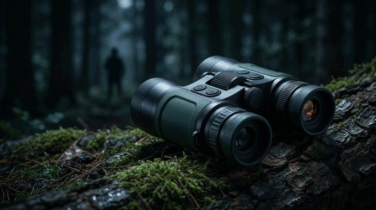
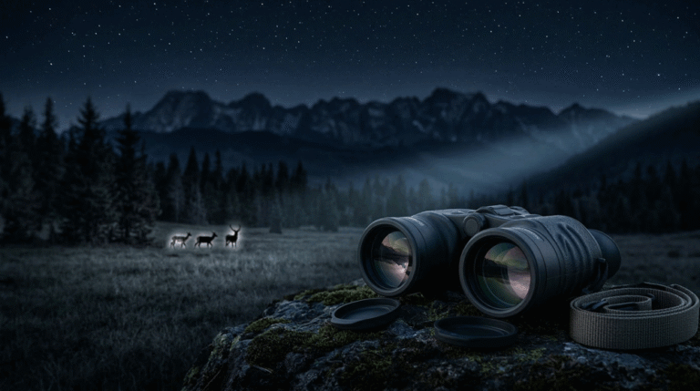
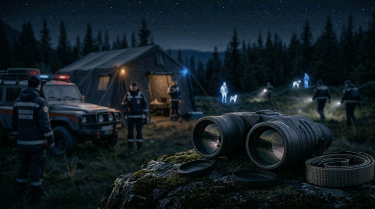
Shorten your inspection routes without giving up proof. We’ll help you standardize an industrial thermal camera workflow—from optics and UI to radiometry, PDFs, and CMMS ingest. Start from our configurable Thermal camera module platform, explore fusion with a Laser Rangefinder Module, and talk with our team about fleet options that complement Thermal Monoculars, Thermal Binoculars, or a contractor-ready Thermal Clip-On Sight kit for crossover field use.