Industrial utilities are moving from periodic handheld inspections to permanent industrial online thermal imaging system deployments in substations and cable networks. Once cameras stay on 24/7, the main engineering question is no longer only image quality. It becomes:
Table of Contents
ToggleWhat temperature do we alarm at, how fast, and what should the system actually trip or interlock?
Setting alarm thresholds and trip logic is critical. If thresholds are too low, operators drown in false alarms and learn to ignore them. If they are too high, a single failure can damage transformers, switchgear, or overhead lines before anyone reacts.
This article explains how to design alarm levels, logic, and integration for power transmission and distribution (T&D) using online thermal imaging and temperature monitoring camera technology. It is written from the perspective of a China-based OEM/ODM manufacturer supplying thermal imaging modules and integrated systems for global utility customers.
Industry pain points in power T&D thermal monitoring
Manual inspections versus 24/7 risk
Most utilities start with handheld thermal cameras and route-based inspections. Technicians walk through the yard, scanning:
- Busbars and jumpers
- Disconnect switches and terminations
- Transformer bushings and cooling systems
- Switchgear rooms and cable joints
This approach works, but only captures a snapshot in time. Many faults develop quickly during peak load, storms, or switching operations—exactly when no one is in the yard with a camera.
Online thermal imaging addresses this gap, but introduces new challenges:
- How to convert continuous temperature data into actionable alarms
- How to prevent nuisance alarms from weather, load swings, or reflections
- How to integrate alarms with SCADA and protection systems safely
QC and supply-chain risks
Once an online system is deployed, utilities expect it to run for 10–15 years. Inconsistent calibration, component changes, or poor firmware design can undermine confidence in the alarms.
For that reason, many T&D operators prefer working with a stable Chinese factory that:
- Supplies module-level products such as thermal imaging modules
- Has clear processes for calibration, QA, and long-term availability
- Can support OEM/ODM customization without sacrificing quality
Compliance, safety, and audit pressure
Regulators and insurers increasingly expect evidence that critical connections and transformers are monitored continuously. An industrial online thermal imaging system offers strong documentation, but only if thresholds, logic, and event records are designed correctly.
What is an industrial online thermal imaging system in T&D?
Working principle
At each monitoring point, a temperature monitoring camera or full thermal camera uses an uncooled VOx microbolometer:
- Infrared lenses focus long-wave IR radiation (8–14 μm) onto the sensor array.
- Each pixel converts radiation into a resistance change.
- Electronics digitize the signal and apply calibration and non-uniformity correction.
- Firmware converts this into temperature data and thermal images.
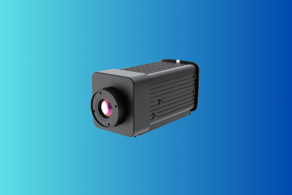
In many systems, each camera is built around a compact thermal imaging module designed for OEM integration into substation-rated housings.
System architecture in power transmission and distribution
A typical industrial online thermal imaging system in T&D includes:
- Field devices
- Fixed thermal cameras or temperature monitoring cameras focused on switchgear, busbars, or transformer bushings.
- Weatherproof housings, sometimes with heaters or blowers.
- Communication network
- Ethernet/PoE, fiber, or industrial serial links from cameras to substations or control buildings.
- Processing and HMI
- Servers that receive thermal images and compute area temperatures, trends, and alarms.
- Operator interfaces in control rooms or SCADA workstations.
- Trip and interlock logic
- Outputs to SCADA, protection relays, or PLCs.
- Configurable alarm stages (warning, alarm, trip) with time delays and latching.
Alarm thresholds sit at the heart of this architecture: they convert raw camera data into reliable decisions for operators and protection systems.
Key specs and technical factors that affect alarm thresholds
Measurement accuracy and uncertainty
Every industrial thermal camera has a finite accuracy, often around ±2 °C or ±2% of the reading under calibrated conditions. In T&D yards, additional error sources appear:
- Emissivity differences between painted busbars, bare aluminum, and connectors
- Reflections from nearby insulators, steel structures, or the sun
- Atmospheric effects over long distances
When designing alarm thresholds for an industrial online thermal imaging system, engineers should:
- Treat the spec as a boundary, not a guarantee in all conditions.
- Add safety margins when defining alarm levels.
- Use trend detection (change over time) in addition to absolute limits.
Region-of-interest (ROI) definition
Alarm logic rarely uses raw pixel data. Instead, the system defines ROIs corresponding to real components:
- Connector pads
- Cable terminations
- Bushing skirts
- Switch contacts
For each ROI, the system may compute:
- Maximum temperature
- Average temperature
- Temperature difference to ambient or reference phases
Correct ROI definition is essential; poorly placed ROIs can “look” at the sky or an insulator instead of the conductor and generate misleading readings.
NETD and smallest detectable anomaly
NETD (Noise Equivalent Temperature Difference) influences how small a temperature rise you can reliably detect, especially at longer distances.
- Lower NETD (e.g., ≤ 40 mK) allows earlier detection of subtle warming.
- Higher NETD requires larger temperature changes to cross the noise floor.
In practice, when designing thresholds:
- Use lower NETD cameras for high-value assets (GCBs, large transformers).
- For less critical applications (general yard scanning), slightly higher NETD may still be acceptable.
Dynamic range, ranges, and saturation
Substations experience wide temperature variations:
- Ambient from –30 °C to +50 °C (or more, depending on geography).
- Component temperatures from near ambient up to 100–150 °C during faults.
If the camera’s chosen temperature range is too narrow, hot spots can saturate, flattening the image and invalidating thresholds. A well-designed industrial online thermal imaging system handles:
- Automatic or controlled switching between low and high ranges.
- Consistent thresholds across range changes (no artificial “jumps”).
Focusing and stability
In T&D environments, cameras are often mounted on masts or building rooftops, focusing on equipment dozens of meters away. Over time, mechanical shifts, temperature cycles, or refocusing may be required.
A motorized focusing design is not mandatory everywhere, but it offers clear benefits:
- Remote refocus after mechanical work or structural changes.
- Optimization for different load conditions when certain ROIs move slightly.
- Compensation for small alignment changes due to temperature-induced movement.
Better focus improves local contrast and makes alarm thresholds more reliable.
Designing alarm thresholds for industrial online thermal imaging
Alarm design is part science, part engineering judgment. Below is a structured approach used in many power T&D projects.
Step 1 – Decide between absolute and relative thresholds
Absolute thresholds trigger at a fixed temperature (for example, 90 °C on a bushing connector).
Relative thresholds trigger when a component’s temperature rises relative to:
- Ambient temperature
- Other phases (phase imbalance)
- Its own historical baseline (trend-based)
Best practice usually combines both:
- A relative early warning (e.g., 15–20 °C hotter than other phases)
- An absolute alarm or trip level (e.g., 100 °C on a particular contact type)
This combination accommodates seasonal changes and load variability better than a single fixed value.
Step 2 – Define alarm stages
A robust industrial online thermal imaging system typically uses multiple stages:
- Advisory / pre-alarm
- Non-latching notification
- Encourages inspection during the next shift or routine patrol
- Alarm
- Latching event recorded in SCADA
- May trigger increased monitoring, load reduction, or switching plans
- Trip / interlock
- Optional, and used with caution
- Initiates automatic actions: load shedding, switching, or blocking of manual operations
Not all utilities implement automatic trips from thermal systems; many prefer thermal alarms to feed into operator decision-making first.
Step 3 – Add time delays and filtering
Temperature is slower than current. Small, short-lived spikes (e.g., caused by birds, insects, or brief reflections) are not worth tripping.
To stabilize alarms:
- Apply time delays, such as “condition must hold for at least 30–300 seconds.”
- Use temporal filtering, averaging over a moving window.
- Combine with image validation (for example, alarm only if a contiguous cluster of pixels exceeds the threshold).
These techniques reduce nuisance alarms and improve trust in the system.
Step 4 – Differentiate assets and risk levels
Each asset class has different failure modes and acceptable temperatures. Example (illustrative only):
| Asset type | Pre-alarm concept | Alarm concept |
|---|---|---|
| Busbar joints | ΔT to other phases | Higher ΔT or reaching max design temperature |
| Cable terminations | ΔT to ambient | ΔT to ambient + absolute cap |
| Transformer bushings | ΔT to tank / oil temperature | ΔT + approach to manufacturer limit |
| Switch contacts | ΔT to incoming/outgoing conductors | Large ΔT or hot spot growth over time |
Final values must follow local standards, manufacturer data, and field experience; online cameras simply provide continuous, objective data.
Step 5 – Validate thresholds in field trials
Before rolling out across a grid, many operators:
- Implement the industrial online thermal imaging system in one pilot substation.
- Run it in “monitor-only” mode with alarms logged but not acted upon.
- Compare alarms to actual inspections and load data over weeks or months.
During this phase, thresholds are tuned, false alarm patterns are identified, and operating procedures are written.
Trip and interlock logic: integrating thermal alarms with protection
Separation of protection and condition monitoring
Traditional protection relays act on currents, voltages, and frequencies according to established standards. An online thermal imaging system adds condition monitoring, not primary protection.
Good practice is to:
- Keep thermal alarms and critical protection functions logically separated.
- Use thermal alarms to modify operating limits, not replace core protection.
- Ensure any automatic trips have clear engineering justification and redundancy.
Logical combinations and voting
Where automatic action is justified, utilities may implement:
- Voting logic – for example, require both high thermal alarm and high load before tripping.
- Cross-checks – only trip if the same ROI has shown elevated temperature for a defined time and a previous pre-alarm was acknowledged.
This avoids tripping on isolated measurement anomalies.
Fail-safe behavior
Design must consider what happens if:
- A camera or communication link fails.
- Calibration data becomes invalid.
- The system experiences a software error.
Most utilities choose fail-as-alarm for condition monitoring (inform operators if a device is unavailable), but not fail-as-trip; trips should not occur solely because the thermal system failed.
Application scenarios for online thermal alarms in T&D
Substations and busbar systems
Fixed cameras monitor:
- Busbar connections
- Disconnect switches and contact fingers
- Cable terminations on GIS or AIS equipment
Alarm thresholds often focus on phase imbalance (one phase hotter than others) and absolute limits based on equipment ratings. The industrial online thermal imaging system provides detailed images that help engineers distinguish between contact issues, overloads, and localized heating.
Overhead lines and connectors
Thermal cameras mounted on towers or structures can watch:
- Dead-end and suspension clamps
- Jumpers and splice connectors
- Mid-span joints near crossings
Here, range and focusing are critical. Alarms must account for wind, solar loading, and changing viewing angles. It is common to start with advisory alarms and use manual confirmation before any trip is considered.
Transformers and reactors
Temperature monitoring cameras watch:
- Bushings and top caps
- Radiators and cooling fans
- Tap-changer compartments
By correlating thermal alarms with load and oil-temperature data, operators can detect:
- Developing contact problems in bushings
- Blocked cooling paths or fans that fail to start
- Abnormal hot spots on tank surfaces
Trip logic is usually conservative: thermal alarms initiate detailed inspection or controlled load reduction rather than immediate tripping.
Switchgear rooms and cable terminations
Indoor environments allow closer mounting distances and more precise ROIs. Online thermal systems can:
- Detect loose joints in LV/MV switchgear
- Monitor cable terminations and bus duct joints
- Support maintenance planning and condition-based inspections
Here, thresholds may be tighter, because ambient conditions are more stable and load profiles more predictable.
How to choose a China industrial online thermal imaging system manufacturer or OEM supplier
Engineering and customization ability
Power utilities and integrators rarely need identical systems. Look for a China supplier that can:
- Offer modular thermal imaging modules with different resolutions and optics.
- Customize ROIs, alarm algorithms, and communication interfaces.
- Provide dedicated “temperature monitoring camera” variants for T&D applications.
Control of sensor, lens, and firmware
Ask whether the manufacturer:
- Has reliable sensor sourcing and second sources.
- Designs or closely manages lens production and testing.
- Develops firmware in-house and can adapt it for your logic needs.
A manufacturer with strong R&D is more likely to support long-term firmware updates and custom trip logic.
QA/QC: calibration, aging tests, and EMC
For outdoor T&D environments, QA/QC is as important as specs. Review:
- Calibration procedures and references (blackbody, traceable standards).
- Environmental and vibration testing methods.
- EMC/EMI tests and compliance with IEC/EN standards.
Pages such as Manufacturing & Quality show how seriously a supplier treats production control and traceability.
Lifecycle, delivery, and OEM/ODM cooperation
An online thermal system is a long-term investment. Choose partners who:
- Communicate product lifecycles and change-management processes.
- Support OEM/ODM cooperation models described on Why Choose Us.
- Can deliver spare units and support across multiple countries, including wholesale channels where needed.
Gemin Optics as your OEM/ODM partner for industrial online thermal imaging
Gemin Optics is a China-based manufacturer focusing on thermal and rangefinding technology for demanding B2B applications. Our portfolio includes:
- OEM thermal imaging modules used in industrial online systems and portable devices.
- Laser rangefinder modules that can be fused with thermal channels for advanced solutions.
- Application support for utilities, industrial plants, and integrators.
Full-stack engineering support
For industrial online thermal imaging system projects, we support partners with:
- Optics, FOV, and placement guidance in substation environments.
- ROI design and calibration strategies for specific asset types.
- Assistance in translating utility maintenance rules into alarm thresholds and trip logic.
Because we operate as an OEM/ODM supplier, we can adapt our modules and firmware to your control systems and communication standards.
Quality, documentation, and trust
Our Manufacturing & Quality practices include calibration, aging tests, and detailed documentation. Combined with the OEM/ODM cooperation models on Why Choose Us, this gives power utilities and integrators confidence that their thermal monitoring infrastructure is built on a stable foundation.
For commercial and technical discussions, our Contact page connects you directly with our engineering and sales teams.
FAQ: B2B questions about industrial online thermal imaging systems
1. What detector resolution is recommended for an industrial online thermal imaging system in T&D?
For most substation and switchgear applications, 384 × 288 offers a good balance of coverage and detail. For large yards or long distances to overhead connectors, utilities often choose 640 × 512 to maintain enough pixels on critical components.
2. How accurate are temperature readings for trip decisions?
Industrial thermal cameras typically achieve ±2 °C or ±2% under calibrated conditions, but field accuracy depends on emissivity, reflections, and viewing angle. As a result, online systems usually use multiple alarm levels and trend analysis rather than a single “hard trip” temperature.
3. Can Gemin Optics customize thresholds and logic for our SCADA system?
Yes. As an OEM/ODM supplier, Gemin Optics can provide programmable alarm logic at the camera or server level, along with SDKs and protocol documentation. We can help map thresholds to your SCADA tag structure and existing operating procedures.
4. What is the difference between a full thermal camera and a simpler temperature monitoring camera?
A full thermal camera provides high-resolution images and flexible ROIs. A simpler temperature monitoring camera may use fewer pixels or pre-defined zones but is easier and cheaper to integrate. Both can belong to the same industrial online thermal imaging system and share common firmware and interfaces.
5. What certifications are required for use in high-voltage environments?
Requirements vary by region, but CE, FCC, and RoHS are common baselines. For high-voltage yards, EMC and insulation coordination must be considered. Gemin Optics collaborates with integrators to align camera and enclosure designs with applicable IEC standards.
6. How stable is the supply chain for long-term deployments?
Gemin Optics manages key components and maintains roadmaps to support long-term OEM projects and wholesale partners. Product changes are communicated in advance so operators can plan upgrades or spares.
7. How does warranty and after-sales service work for B2B buyers?
Industrial customers receive defined warranty periods, technical support, and options for repair or replacement. For large fleets, service models and spare strategies are discussed at the contract stage.
Work with a China industrial online thermal imaging system manufacturer you can trust
Designing alarm thresholds and trip logic is what turns an industrial online thermal imaging system from a passive camera network into an active protection layer for power transmission and distribution.
As a China-based manufacturer with strong R&D and OEM/ODM experience, Gemin Optics can help you:
- Select and integrate temperature monitoring cameras based on your assets and risk profile.
- Translate maintenance rules into practical alarm stages and trip logic.
- Build scalable, standards-compliant solutions that can grow from one pilot substation to entire grids.
To move your project forward:
- Contact our engineering team through the Contact page to discuss your industrial online thermal imaging system requirements.
- Share your OEM/ODM specifications so we can recommend suitable modules and architectures.
- Explore long-term OEM/ODM solutions on Why Choose Us and build a reliable foundation for your next-generation thermal monitoring strategy.